Solarimaging
Introduction
Solar imaging has been a passion of mine since my school days. The sight of the mighty sun temporarily obscured, and events like the Venus transit, has always left me in awe.
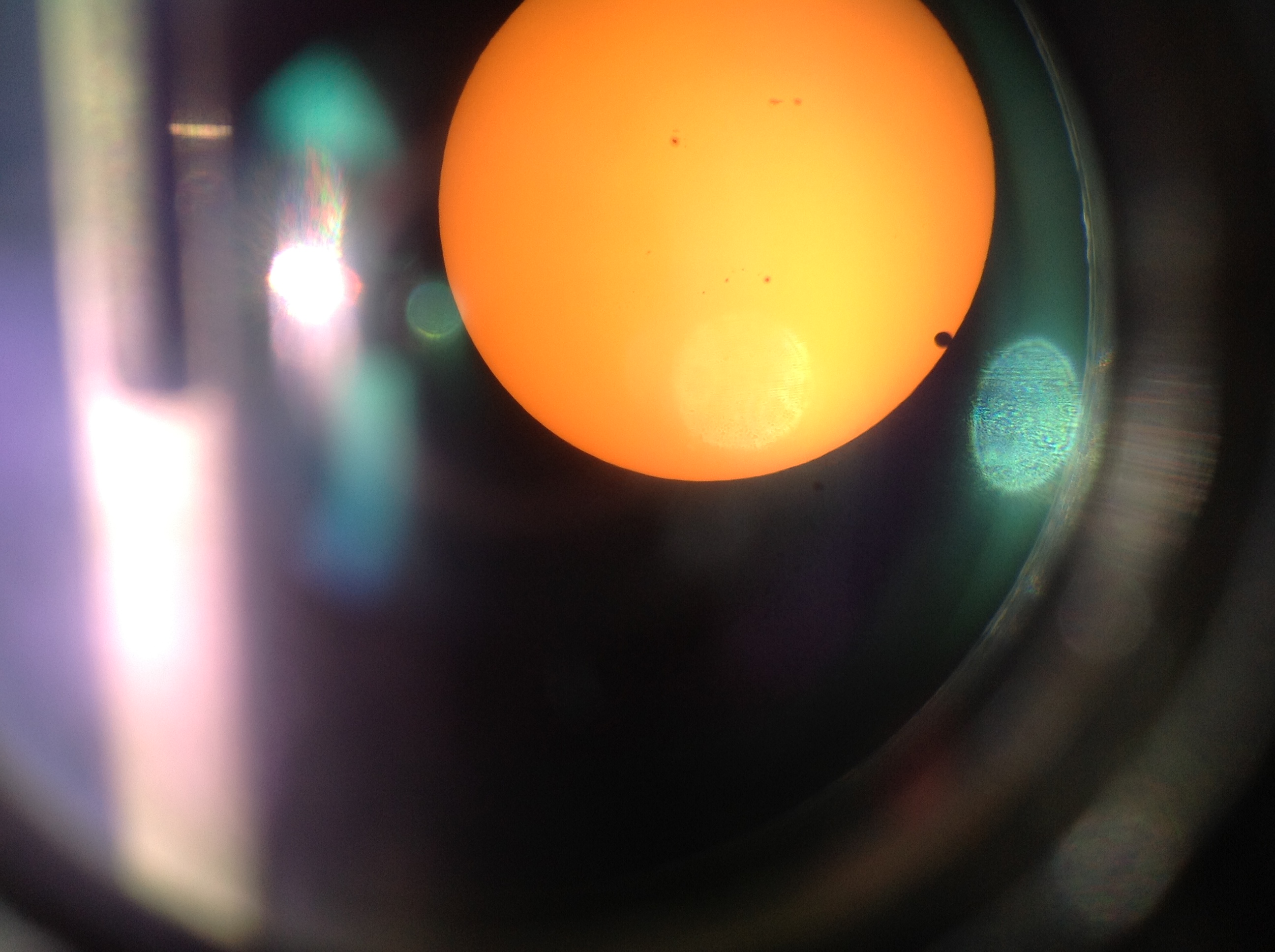
Here is a shot taken back in 2012 Venus transit with an iPad 3 gen.
Whenever I have the chance to explore solar imaging, I’m on the lookout for imaging system to capture these celestial moments. In 2020, during a two-week COVID-19 quarantine at a hotel, I embarked on a project to construct a solar tracking camera. This camera was built using the Raspberry Pi HQ camera and Raspberry Pi 4:
With RPI tracking the Sun pic.twitter.com/xhnqGD26hS
— will whang🌻 (@will_whang) June 25, 2020
The results were astounding:
Fast forward to 2023, and we’re preparing for two upcoming solar eclipses—one in October 2023 and another in April 2024. This time, I’m taking my solar imaging game to the next level.
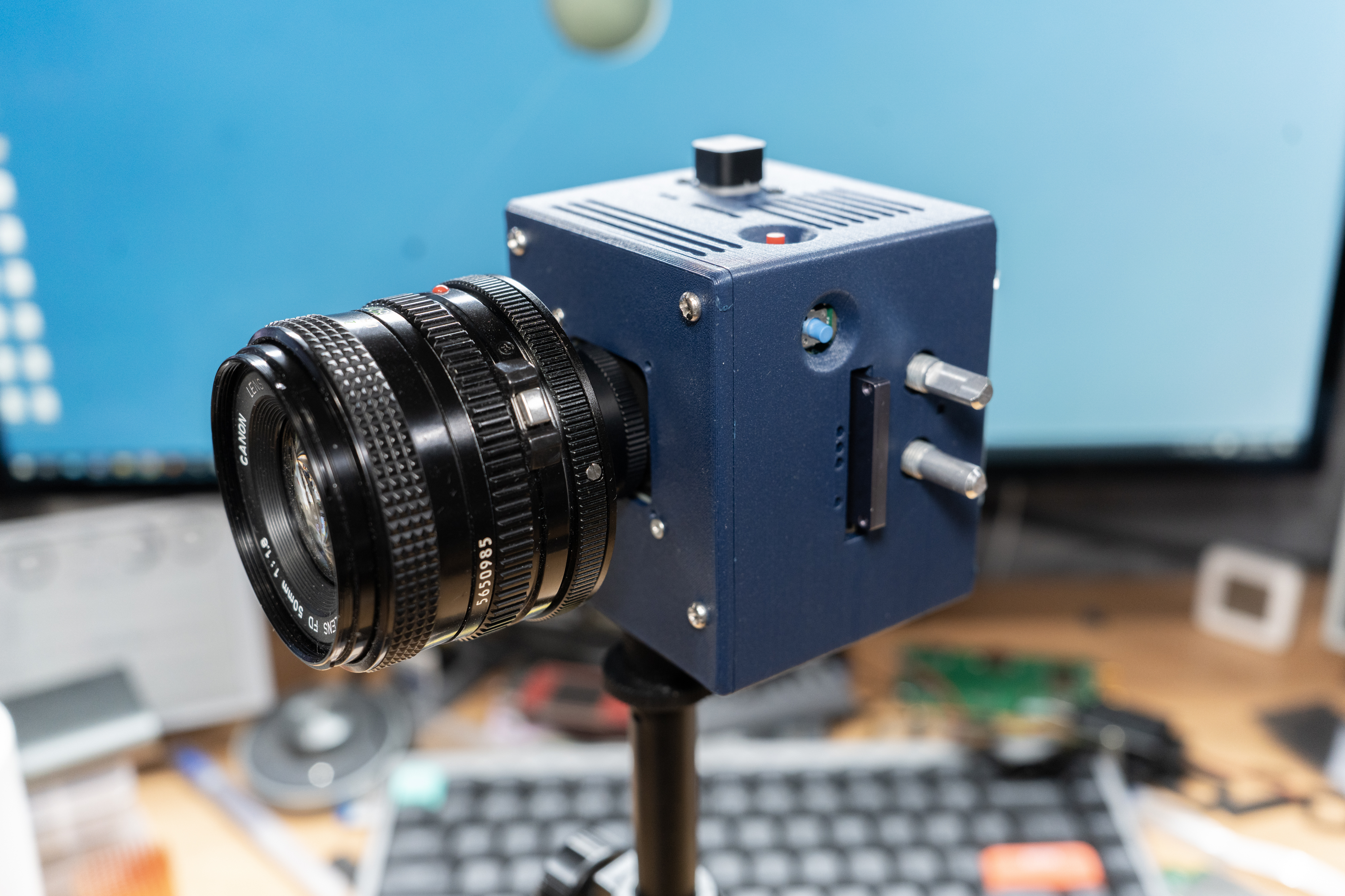
Raspberry Pi Imaging System
With the introduction of the Compute Module 4 (CM4) and its versatile applications, I decided to create a CM4-based camera system that would fit snugly into a compact enclosure:
Block Diagram
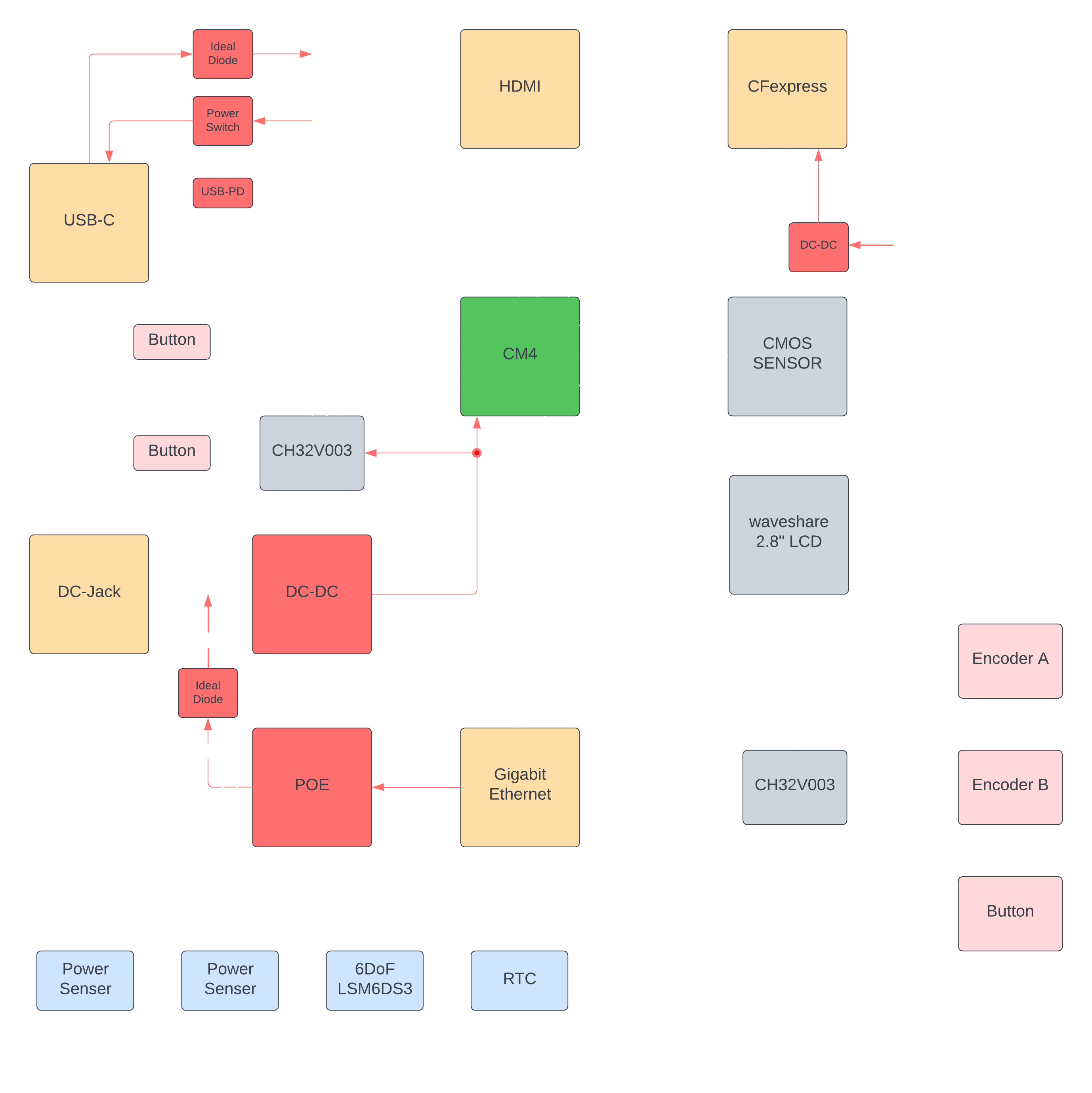
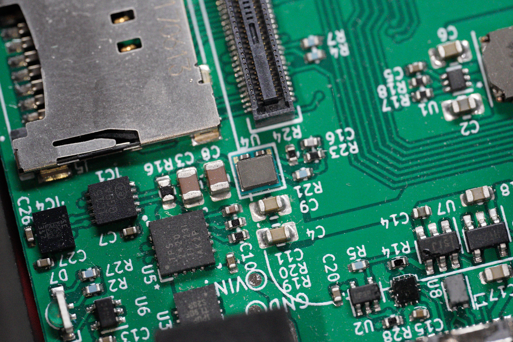
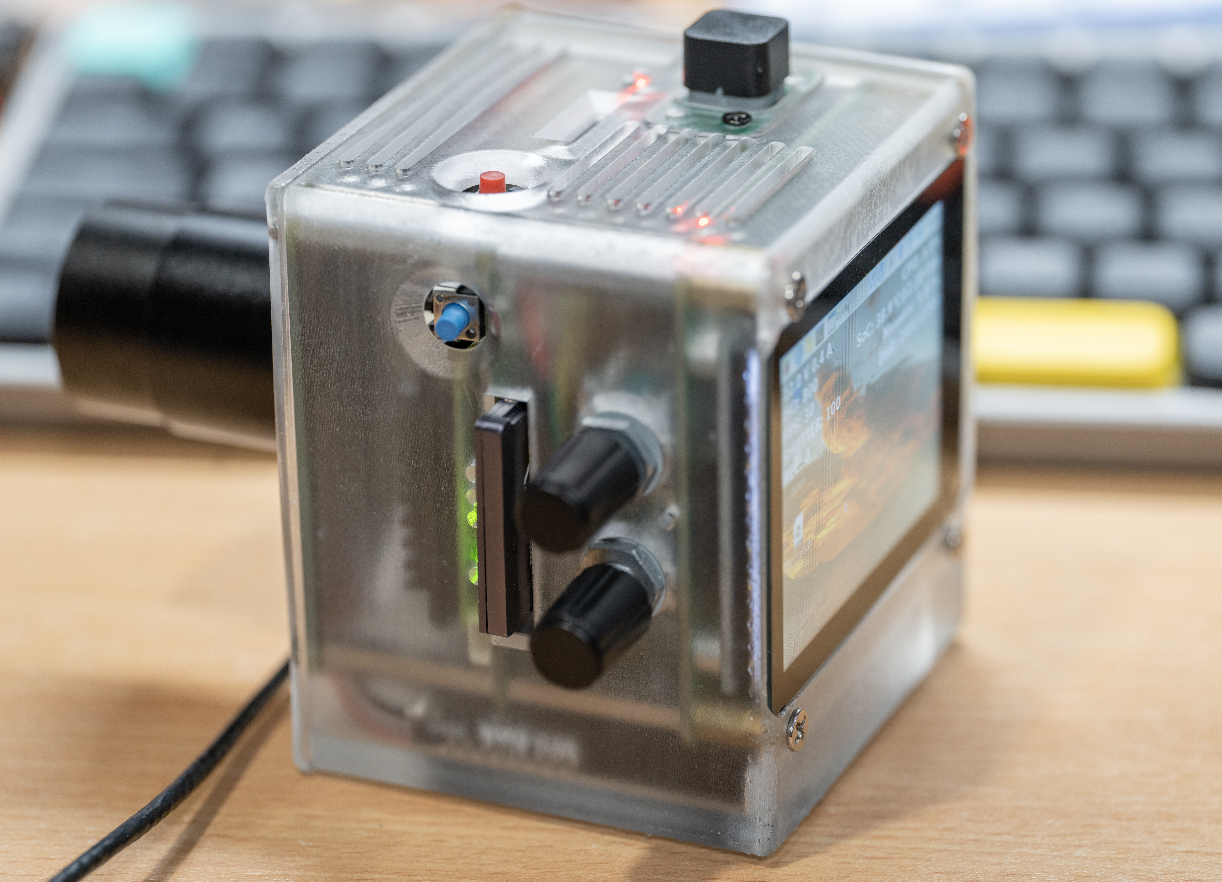
CM4 Camera V3
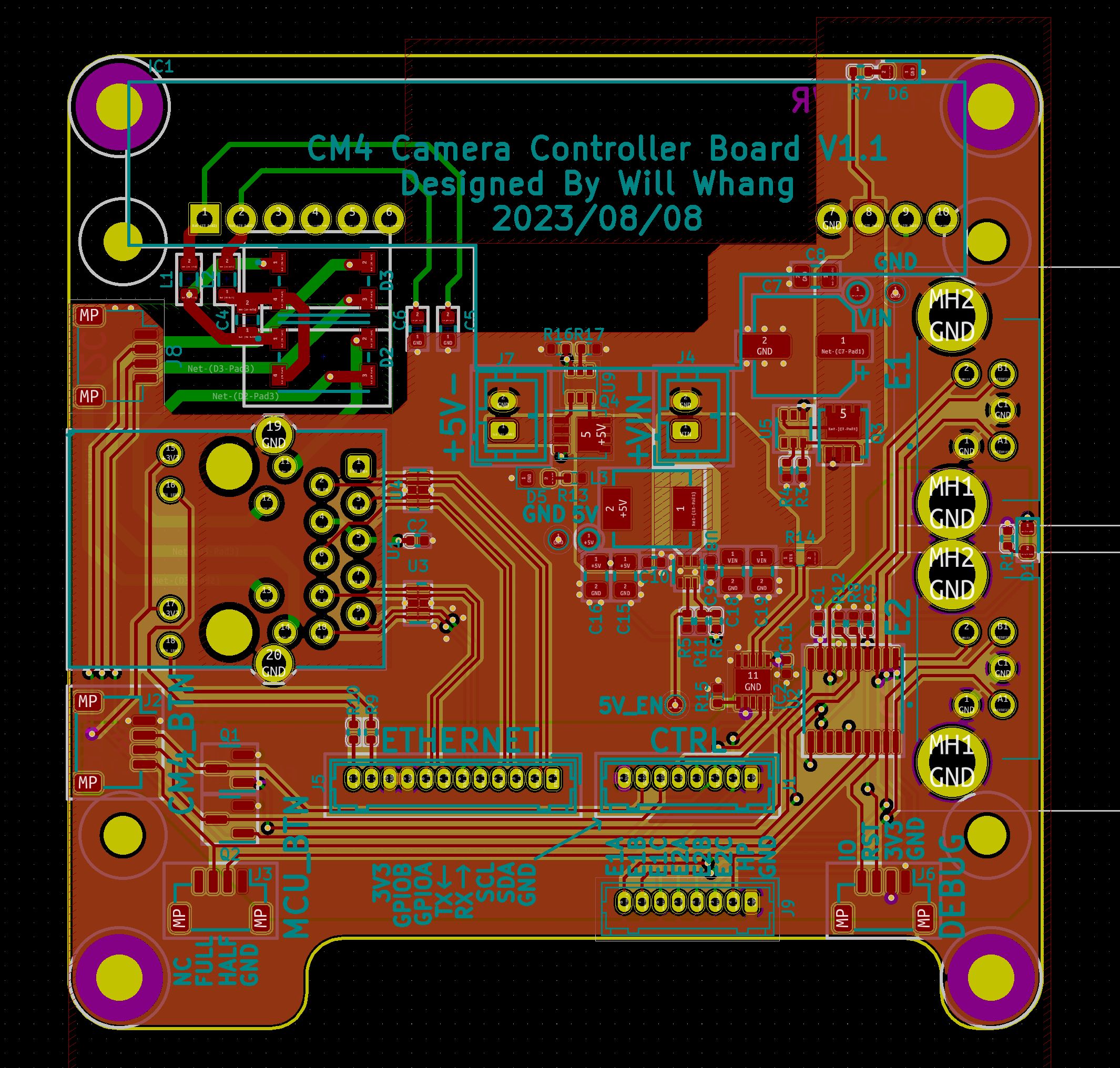
To address space constraints, I divided the board into two components: the Main board and the Controller board + display adaptor. The Main board houses most of the critical components, boasting a 4-lane MIPI Display and Camera FPC header, along with provisions for future EF mount control:
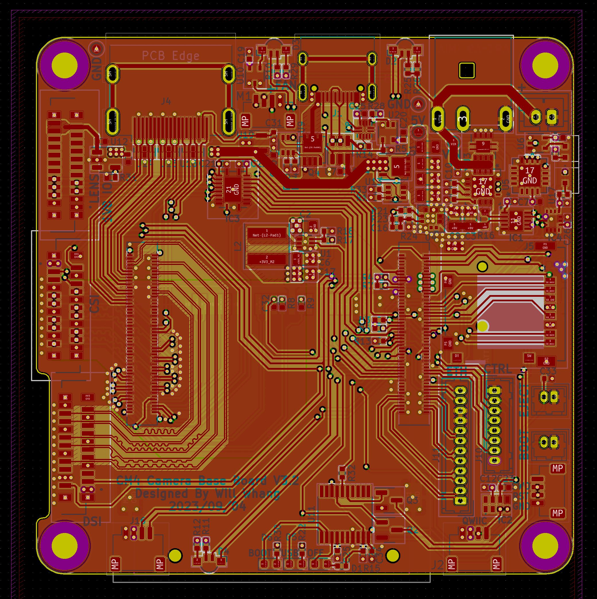
Sidenote: the PCB was manufactured with epoxy filled and caped, so the via is on the pad in some area because I like epoxy filled PCBs.
CFE (CFexpress)
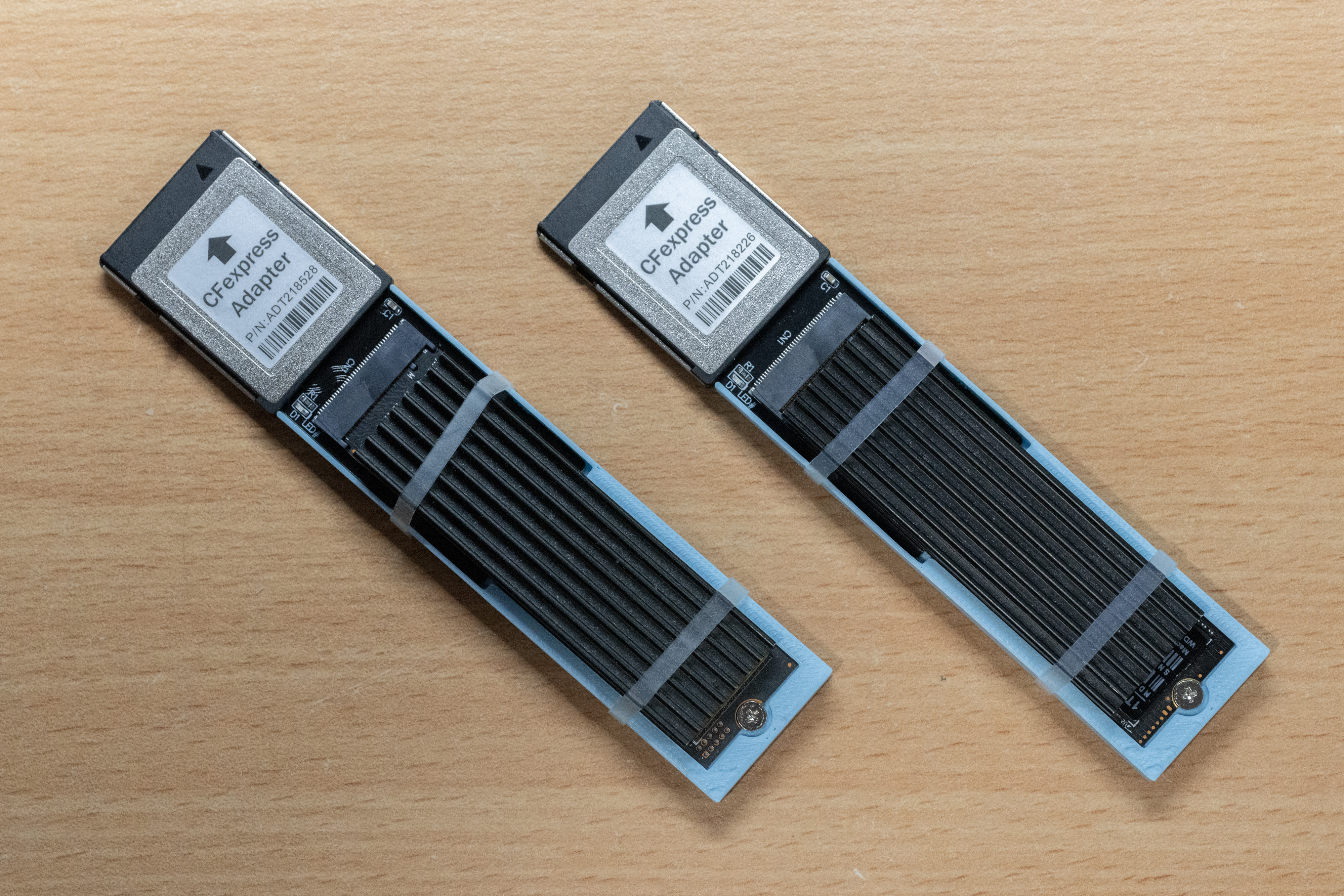
Now, let’s tackle the storage aspect. For the CM4, the only high-speed interface available is PCIe 2.0x1. I had two choices: utilize a USB3.0 controller with an external drive or directly break out PCIe 2.0x1. After careful consideration, it became evident that the external drive option would likely involve an NVMe drive with a USB to NVMe bridge, essentially introducing an unnecessary USB 3 conversion. The bottleneck here is hot-plug capability and finding a suitable connector for easy PCIe device swapping. This is where CFexpress with eject buttons comes into play:
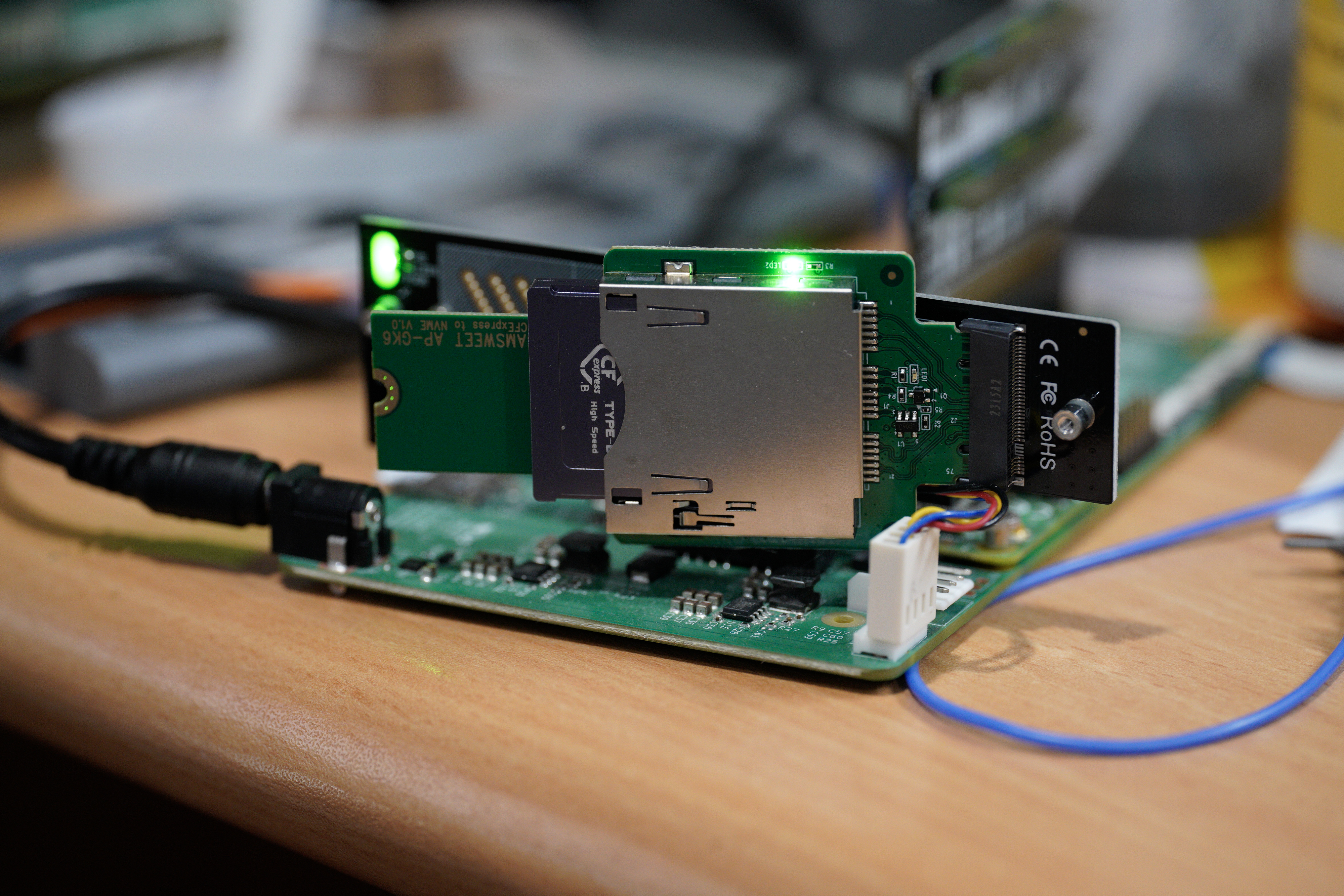
CFexpress essentially combines PCIe with 3.3V power and some card insertion signals. It’s relatively straightforward to make it work with CM4 since it functions as a PCIe device. However, the challenge arises when swapping cards while the system is live. CM4 doesn’t support PCIe hot-swapping. However, a workaround involves unloading the driver in Linux to eject the card, using the insert signal to load the driver, or re-scanning the PCIe device. By incorporating a button to eject the card and connecting the insert signal to CM4, I’ve achieved nearly everything I desired without PCIe hot-plug:
Second feature: Almost hot-plugging CFExpress Card.
— will whang🌻 (@will_whang) August 12, 2023
*The video is showing lspci cmd.
Raspberry Pi computer module 4 doesn't support PCIe hotplug, but with some simple shell script, you can manually eject the PCIe device and rescan the PCIe device to load the driver. So I've add… pic.twitter.com/SwCdjyEJBp
Sidenote: It’s worth noting that I’ve chosen not to use traditional(SD 6.0 and lower) SD cards in my camera design. The reason for this decision stems from the fact that the SD card interface is not particularly fast. My main camera, the A7R4, is limited to the UHS-II interface, and the only way to achieve its maximum potential is by investing in expensive SD cards from Sony, which offer a write speed of around 300MB/s. However, this speed still falls short when dealing with the large files generated by the camera. This past experience has left me somewhat traumatized by the limitations of SD cards. As a result, you won’t find me incorporating them into my camera design.
Controller - CH32V003
In the past, due to silicon shortages, I often resorted to using RP2040 for simple MCU tasks, such as on the NVMe array board and CM4 cluster board. However, with the emergence of ultra-low-cost MCUs like CH32V003, there’s no longer a need to follow that route, both in terms of cost and engineering effort. My only complaint about RP2040 was the number of external components required, which was slightly excessive for my use case. I would be delighted if a SiP version with flash and crystal bundled in the same package were available, simplifying the assembly process.
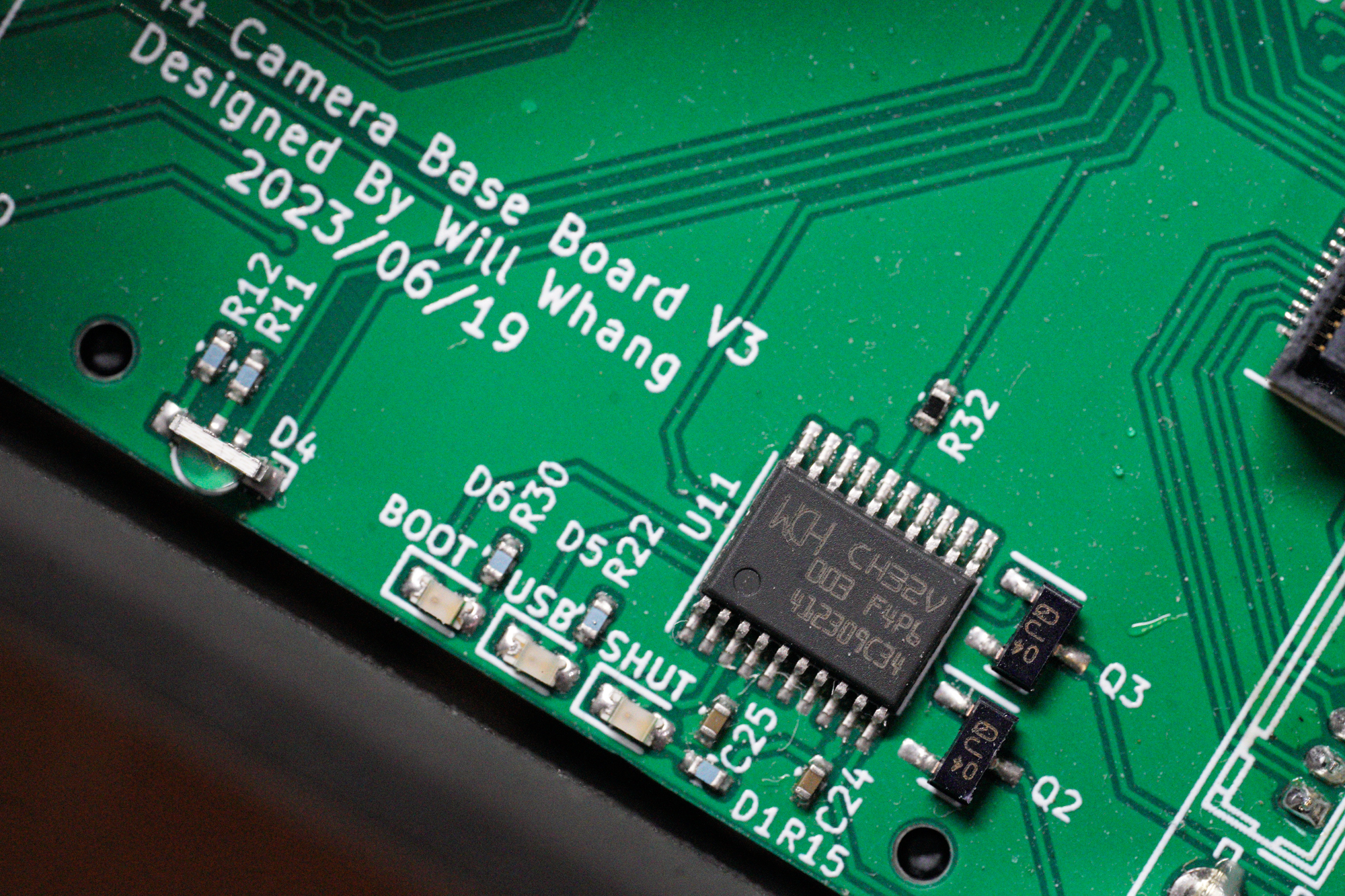
On the Main board, the CH32V003 serves to control CM4’s state, managing shutdown (Disable global_EN), booting, and USB booting. It also provides a power button for handling system shutdowns, boots, and USB booting. Implementing the system is straightforward once you’ve designed the state machine:
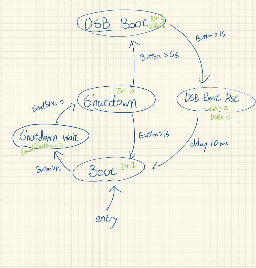
You then fill in the functions in a state machine design pattern in C.
On the Controller board, I’ve incorporated two encoders for adjusting gain and shutter speed, along with buttons for recording and other functions yet to be defined. The CH32V003 reads the encoders and monitors the buttons in a busy loop, transmitting the updates via Serial to CM4:
I’ve also included an Ethernet plug and a POE module on the Controller board, along with an additional 5V DC-DC power supply controlled by CH32V003, in case more current is needed, for example, for TEC cooling.
Miscellaneous Components
For other components, I’ve mostly reused elements from my previous projects. For example, the USB-C PD controller to USB-OTG allows the USB-C port to function as both a USB device and a USB host. Managing power flow is slightly complex due to three power sources available (USB-C/DC-Jack/POE), necessitating the use of multiple ideal diodes on the power path to facilitate on-the-fly power source switching. It’s important to note that the USB-C power input is limited to 5V, because of the complexity to implments high-voltage PD.
POE will provide 12V and DC-Jack power goes to this neet mini DC-DC step-down module that can handles up to 16V and provides 5V 3A:
On the Main board, you’ll also find current sensors to measure system power and input voltage, useful for monitoring battery usage when connected to a camera battery. Additionally, there’s an RTC and a 6-axis gyro+accelerometer, though I don’t quite remember why I added the latter. The newer revisions also include an I2C fan controller.
Enclosure
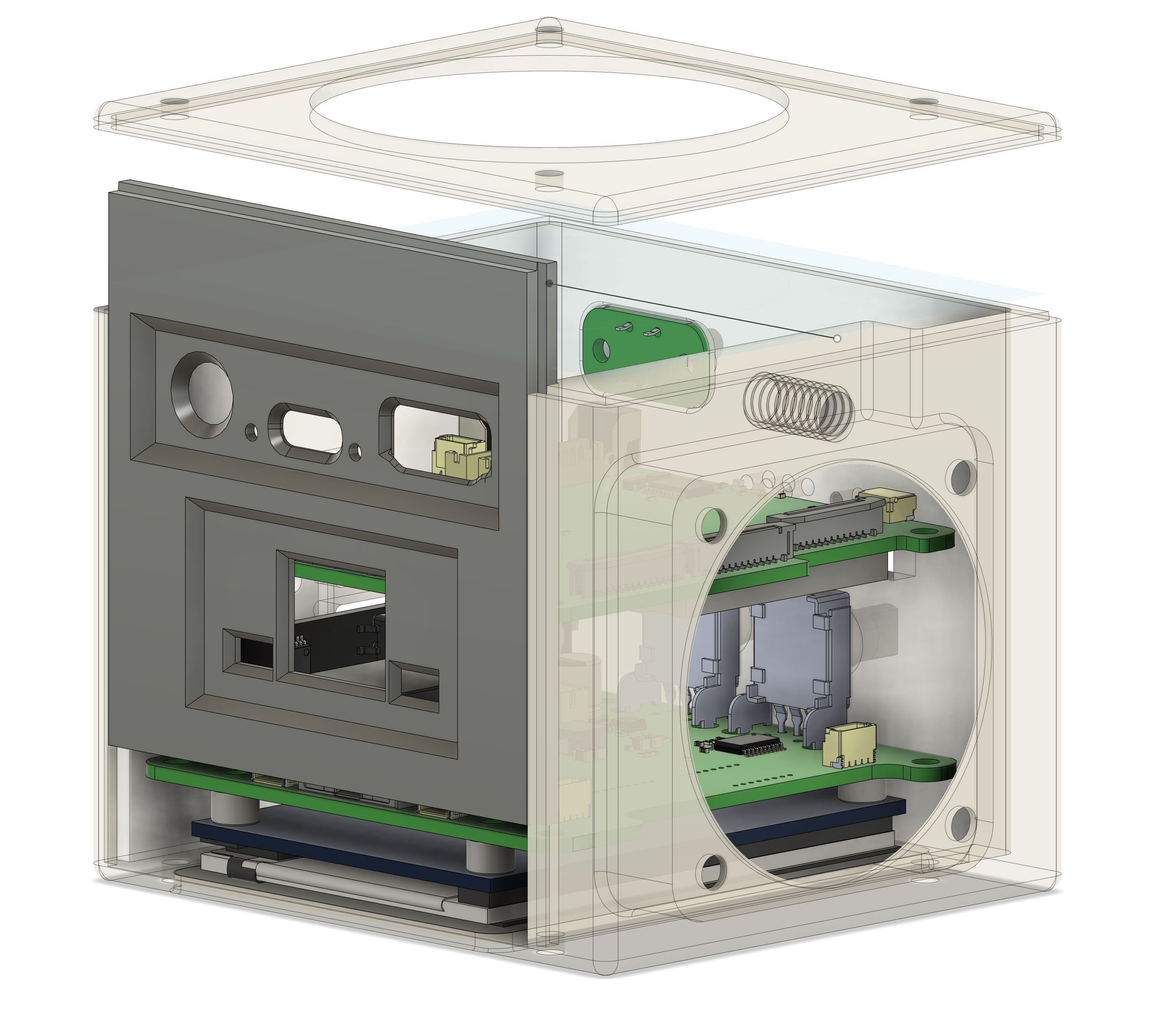
Let’s dive straight into the lessons learned. When I designed the board, I didn’t plan in detail how I was going to create an enclosure with the design. This oversight became evident when I started constructing the enclosure, and several issues cropped up:
-
The HDMI connector protrudes in a way that requires the moving plate to have a cutout for space when it slides in. This doesn’t play well with 3D FDM printing.
-
Two buttons are positioned 90 degrees apart around a corner with an extrusion. Figuring out how to insert the board into the enclosure proved to be a head-scratcher.
-
As for the fan, the only feasible place to put it was on the bottom next to the mounting hole. However, because it’s 1cm thick, the enclosure couldn’t be a simple square cube. (Facepalm)
In the end, I managed to make most of these things work, but I often find myself wishing for a time machine. Additionally, this design isn’t particularly friendly for 3D FDM printing, at least for my Prusa MK3s. After some revisions, I sent it to JLCPCB for 3D resin printing and MJF prints.
OneIncheye + Starlighteye
Now, let’s delve into the core components: the CMOS sensors. The primary reason I designed the OneIncheye and Starlighteye in the first place was to enable these kinds of imaging projects. For those unfamiliar with my code names, OneIncheye is based on the IMX283, a 20MPix one-inch sensor, while Starlighteye is built around the IMX585, a 4K (8MP) 1/1.2” sensor with STARVIS 2 for enhanced low-light performance.
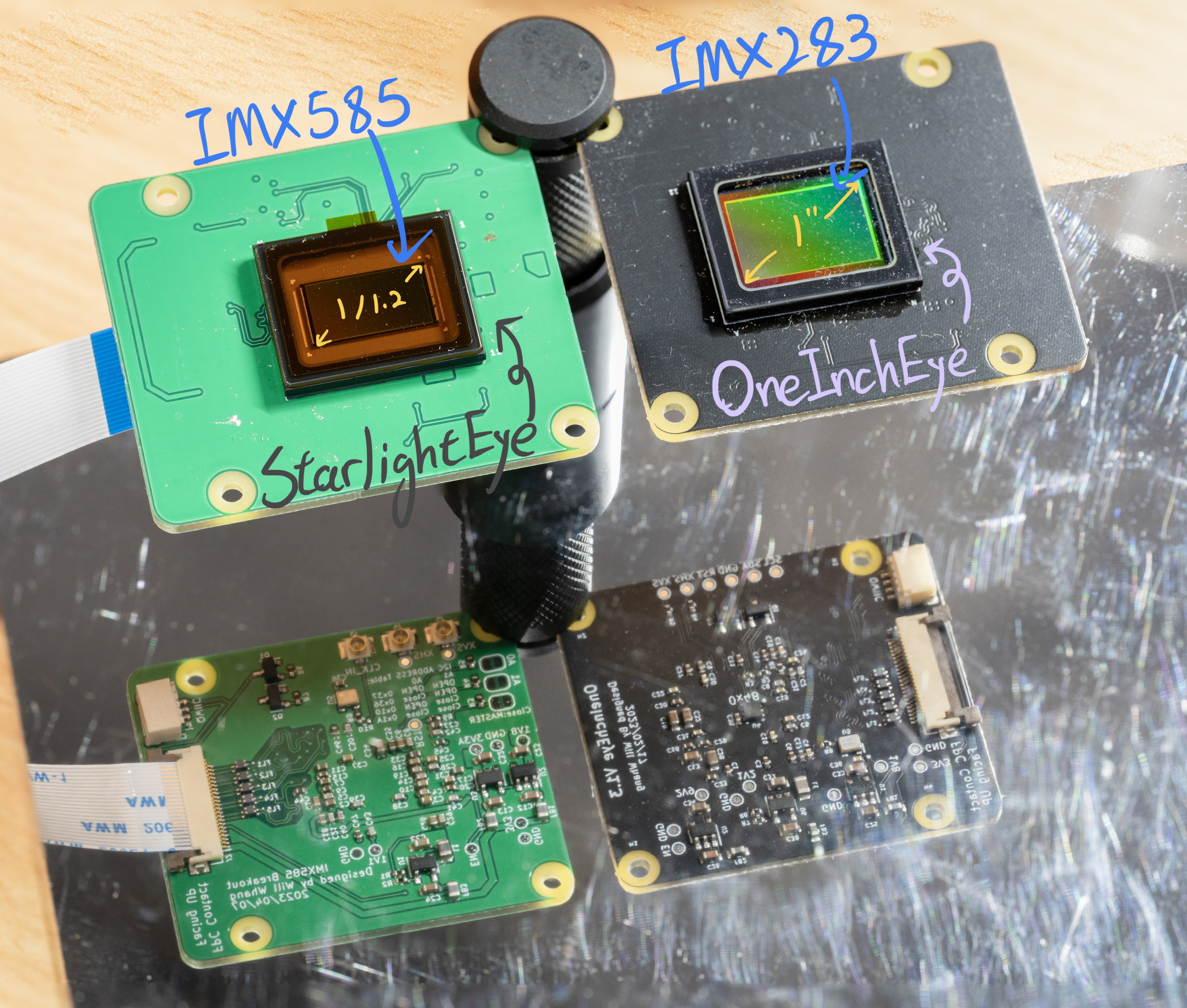
Both sensors are equipped with 4-lane MIPI interfaces to maximize bandwidth. For more information on the sensors, you can refer to the post I previously shared: OneIncheye blog post. Additionally, the sensor designs are open-sourced and available here:
CinePi + Libcamera
Alright, now that we have the hardware ready, it’s time to delve into some software development. Good software implementation is crucial to ensure that no hardware potential goes untapped.
The image capture is built with CinePi, a software based on the Raspberry Pi foundation’s libcamera-apps. CinePi is capable of capturing video as RAW DNG files and also provides control via Redis.
Libcamera - dma_heap
Note: I’m not very familiar with these low-level Linux aspects, so I may be mistaken.
During testing with OneinchEye, I encountered some performance issues with the image buffer. Both memcpy and pixel unpacking were taking longer than expected. For the 20MPix OneinchEye, memcpy took about 70ms for one frame, limiting us to 28FPS at 20MPix if we allocated two CPU cores dedicated for this task. The issue was identified in this forum post about memory caching being disabled, which discusses the performance improvement achieved by using dma_heap-allocated buffers. However, I must admit I didn’t fully comprehend how to implement this. (And you can see my reply to the post asking it back then)
Fortunately, the Raspberry Pi Foundation, specifically Naushir, updated their libcamera-apps with dma_heap buffer support Git commit. This allowed Csaba, the developer behind CinePi, to incorporate the changes and enhance CinePi’s performance. So, the performance bottleneck now primarily depends on how fast you can write to the disk. For 4K, it’s approximately 12MB per frame, which translates to about 33 FPS. For 20MPix, it’s about 12 FPS, assuming a 400MB/s write performance for the disk.
Maxout CMA Memory Size on RPI
It’s known that the Raspberry Pi (RPI) requires Contiguous Memory for the ISP to function, and having more CMA memory allows for more on-the-fly buffer frames. This is important for burst image capture due to the disk IO bottleneck.
For those familiar with CMA, you might think that adding CMA=xxxMB in cmdline.txt would do the job. However, there are two key considerations here:
- VideoCore can only access the first 1GB of memory address, so the CMA range must be under that 1GB.
- When the Linux kernel allocates CMA buffer, anything blocking in the planned contiguous memory can cause allocation to fail.
Upon booting, the CM4 allocates a small chunk of memory to store the device tree, along with the device memory map at the end of the 1GB address (assuming high_peri_mode mode is not enabled). The Linux kernel also needs to allocate memory for itself.
To address this, add device_tree_address to config.txt to manually place the device tree and configure the memory map directly. Here’s an example of an 848MB CMA buffer memory map:
pi@camera6:~ $ sudo cat /proc/iomem
00000000-3b3fffff : System RAM
  00000000-00000fff : reserved
  00210000-0114ffff : Kernel code
  01150000-0154ffff : reserved
  01550000-0186ffff : Kernel data
  02000000-0200dfff : reserved         <--- device tree
  02400000-3b3fffff : reserved         <---  This is actually CMA +  Peripherals memory mapping
here is the config.txt:
device_tree_address=0x2000000
device_tree_end=0x20FFFFF
In cmdline.txt
cma=848M@36M
Note that in my testing, both CMA and the device tree require 4MB alignment memory addresses.
Here’s the forum post discussing the issue, and thanks to cleverca22 and trejan for helping me identify the core issue and mitigation.
So, there’s more to the story. When working with a substantial amount of frame buffer allocation, I encountered another issue: “Not enough buffers provided by V4L2VideoDevice.” What on earth?
As it turns out, the V4L2 kernel has defined a limit in linux/include/uapi/linux/videodev2.h:
#define VIDEO_MAX_FRAME               32
#define VIDEO_MAX_PLANES               8
This limit imposed constraints on the number of buffers that can be provided by V4L2VideoDevice. To address this limitation, I had to recompile the Linux kernel to increase these values. Additionally, I had to modify the corresponding videodev2.h in libcamera to prevent any mismatches that would cause IOCTL errors.
For more detailed discussions on this issue, you can refer to this forum post.
Disk Performance
Now, let’s shift our focus to disk IO. How fast can we go, and where did I get the figure of 400MB/s previously?
Interestingly, I discovered that exFAT on Linux has rather poor performance, while NTFS, although acceptable, results in high CPU usage. To maximize disk IO, I had to use EXT4 directly, along with the flags O_DIRECT and O_WRONLY.
I even crafted a C program to simulate disk writes as cinepi-raw, measuring both IO performance and CPU usage. You can find the program on this Gist page.
But wait, there’s more to discuss: HMB and SLC caching.
I’m not entirely sure if I made a misstep by using CFexpress with DIY NVME SSDs, but upon further consideration, it may not be an ideal choice. Most M.2 2230 SSDs lack the board space placing a memory required for the NVMe drive to store an FTL cache. Moreover, high-capacity drives often use QLC for NAND flash, which isn’t the most optimal for this scenario. To compensate for the lack of on-drive memory, these NVMe utilizes HMB memory, which takes up some of the host memory. During my testing, this setup exhibited a minor degree of performance degradation, and it also consumed part of the CMA memory. I suspect that the memory bandwidth limit in the SOC is causing this performance impact.
As for SLC caching, if you’re familiar with NVMe SSDs, you know that many drives operate part of their storage in SLC mode to boost write speeds. However, once you continuously write beyond the SLC caching size, performance falls back to its raw NAND performance. The issue here is that most large-capacity NVMe 2230 SSDs are designed for handheld consoles, which don’t require constant large continuous writes. They may use something like QLC flash to save costs, and they often market their write speeds using SLC cache numbers, which may not apply to camera usage. When dealing with large data write operations, always check the full-disk write performance, as it might fall below even the PCIe 2.0x1 speed.
Lastly, it’s a bit puzzling that the maximum CM4 throughput I achieved is 400MB/s, given that the PCIe 2.0x1 transfer rate theoretically provides an unencoded bandwidth of 500MB/s.
PCIe 2.0x1 Transfer rate (line rate) = 5.0 Gbit/s / 10 * 8 (10b8b encode overhead) = unencoded bandwidth 4Gbit/s = 500Mbyte/s.
So in the end, I used a CFE to M.2 converter with a custom 3D printed part to hold a large M.2 2280 high performance SSD (P31 and SN750).
cinepi-raw - Redis + Network Streaming
cinepi-raw serves as the core of CinePi, responsible for processing the raw image buffer, saving it as a DNG file, and handling Redis for on-the-fly camera setting control.
A rather intriguing aspect of this process is how the pixels are laid out in memory. While one might expect a 12-bit raw image to look something like this:
RRRRRRRR|RRRRGGGG|GGGGGGGG|......
GGGGGGGG|GGGGBBBB|BBBBBBBB|......
| Where each R/G/B represents a byte and ** | ** marks the byte boundaries, for the SRGGB12_CSI2P (P for packed) format, it actually appears like this: |
R0R1R2R3R4R5R6R7|G0G1G2G3G4G5G6G7|G8G9G10G11R8R9R10R11|......
GGGGGGGG|BBBBBBBB|BBBBGGGG|......
However, DNG/TIFF formats only understand the former layout. Consequently, in cinepi-raw, there is a need to convert the SRGGB12_CSI2P format. Related forum post, and Csaba has now expanded the code to use 64-bit for faster processing as well!
My current cinepi-raw is constructed with two types of threads:
- Encoding Threads: This thread encodes the raw stream data into a DNG file in memory.
- Disk IO Threads: Responsible for writing the memory buffer to disk.
I’ve made a modification to libtiff so that it writes to a memory buffer instead of directly to the disk. This allows us to have some buffer for the disk write operation, which might take longer.
Network Preview Streaming - Post Processing Stages
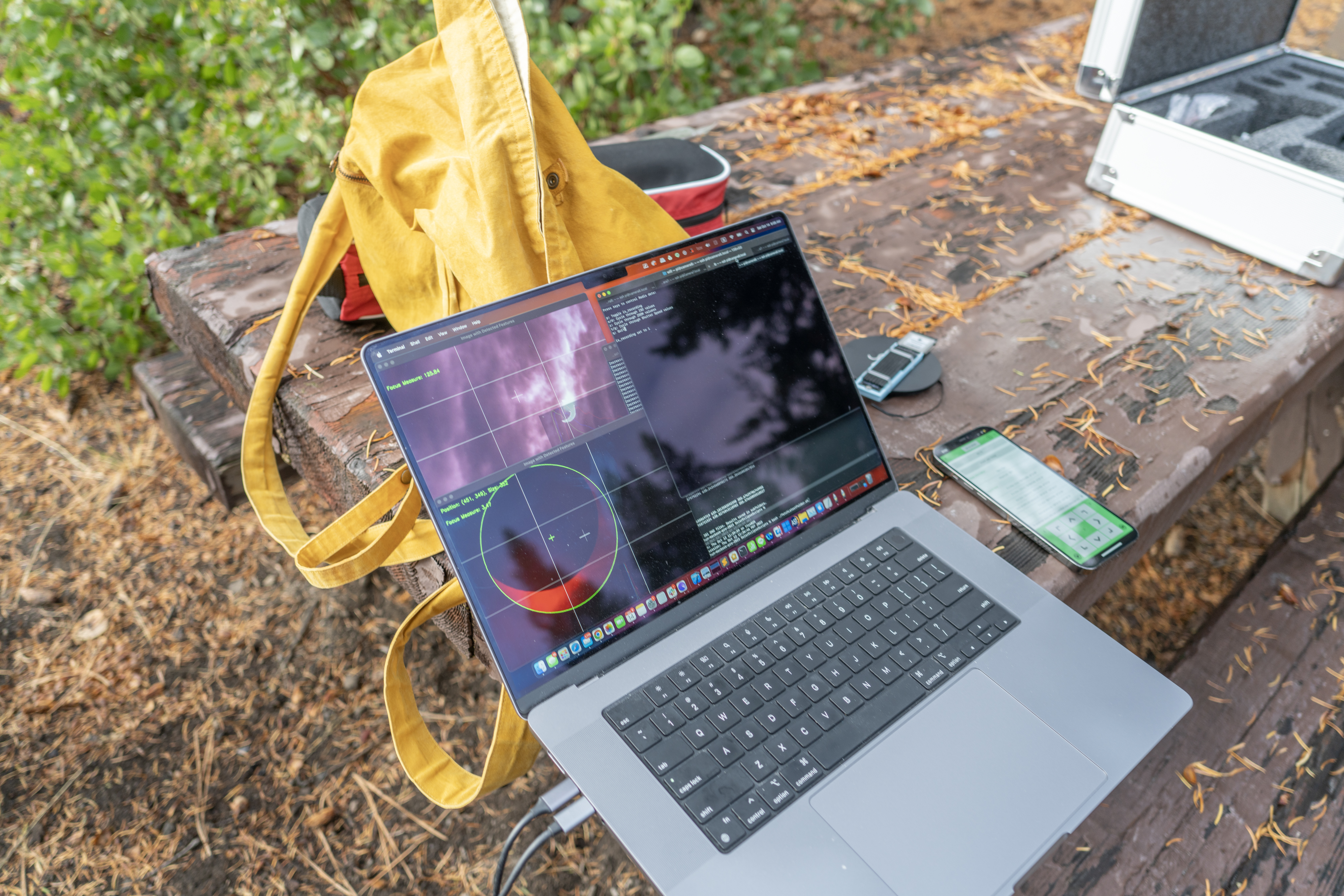
Moving on to the network preview streaming, if you closely examine my work from back in 2020, you’ll notice that I had a live preview on my notebook. Naturally, I pondered how I could achieve the same with cinepi-raw, and it turned out to be much easier than I initially anticipated.
Post-processing stages offer a way to attach custom post-processing code to the image pipeline. The RPI foundation provides examples using OpenCV and some machine learning recognition. In my case, I simply modified the simplest NegateStage. Instead of processing the image, I configured it to stream the image through TCP to my notebook. Additionally, I can set the IP and port in the post_processing_stages JSON config file. Here is the networkPreviewStage.cpp.
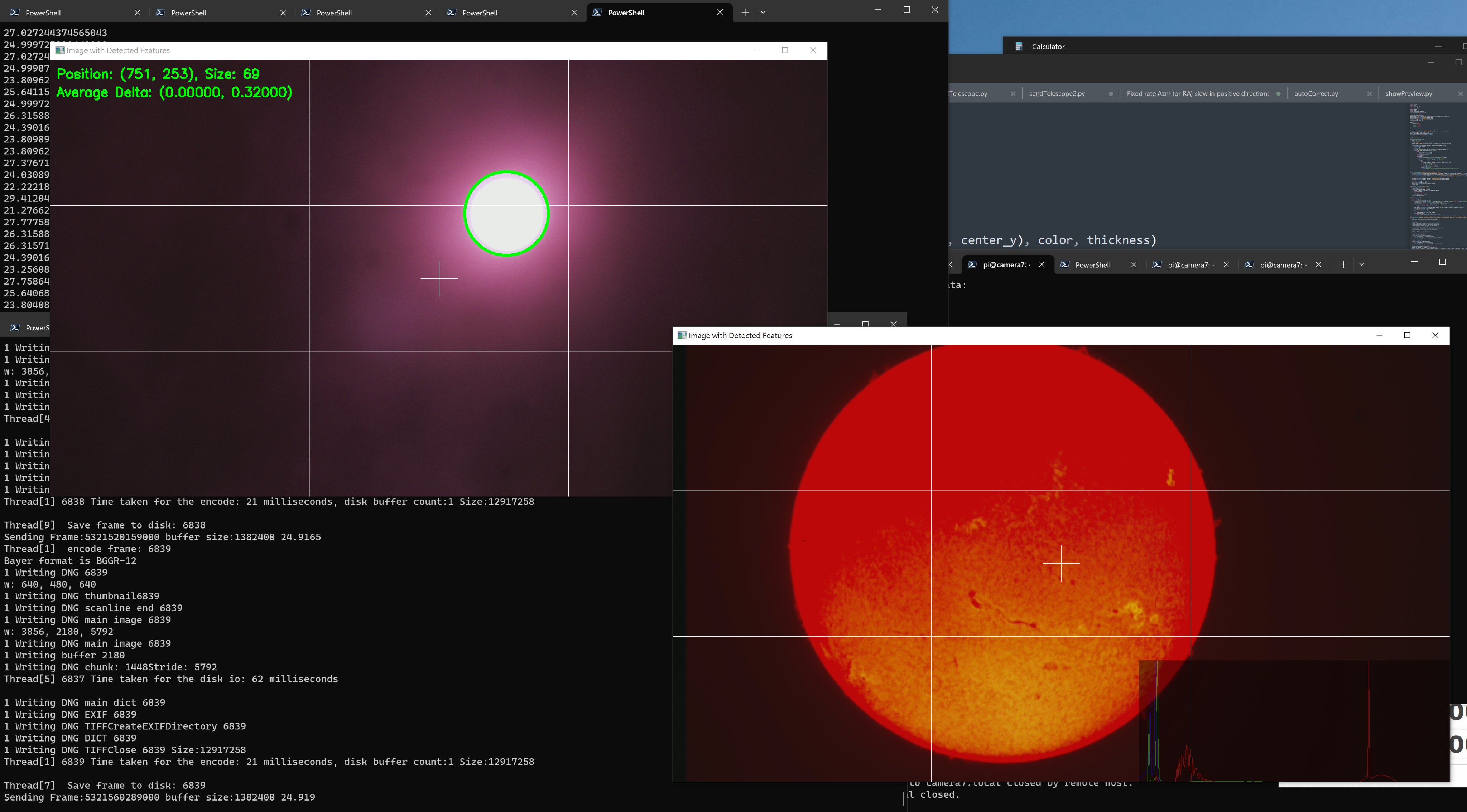
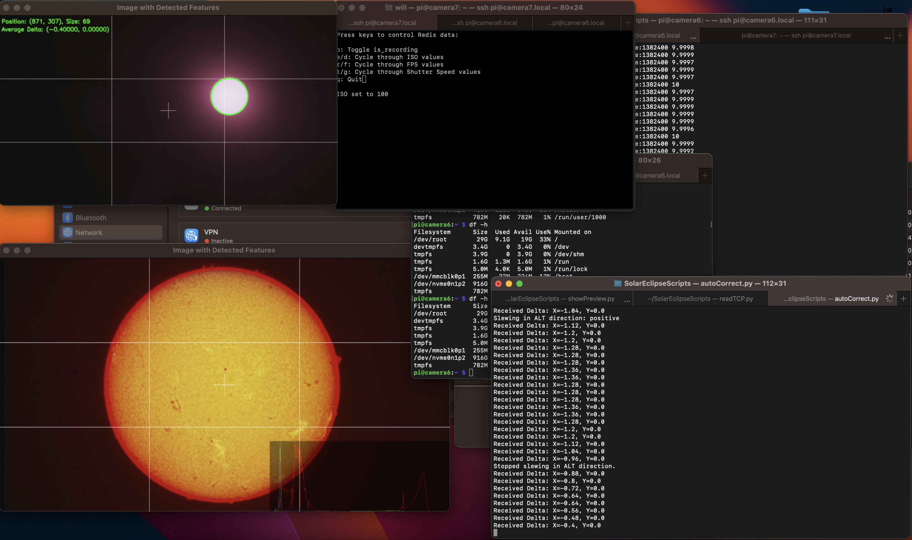
On the receiver side (code), I’ve developed a Python script that opens two TCP ports. One is for configuring the resolution and stride, while the other is for reading the streaming images and displaying them with OpenCV. The script also performs various tasks such as histogram and grid overlay, circle detection, origin drift measurements, and most importantly, focus measurements and focus assistance.
cool kids are having fun with their Pi 5 while I'm still working on something I need next weekend.....
— will whang🌻 (@will_whang) September 30, 2023
libcamera-app is really easy modify, here is the CinePi with IMX585 running 4K @ 25FPS while streaming to my PC using a simple post_process code to dump YUV pic.twitter.com/tTgx1yqib4
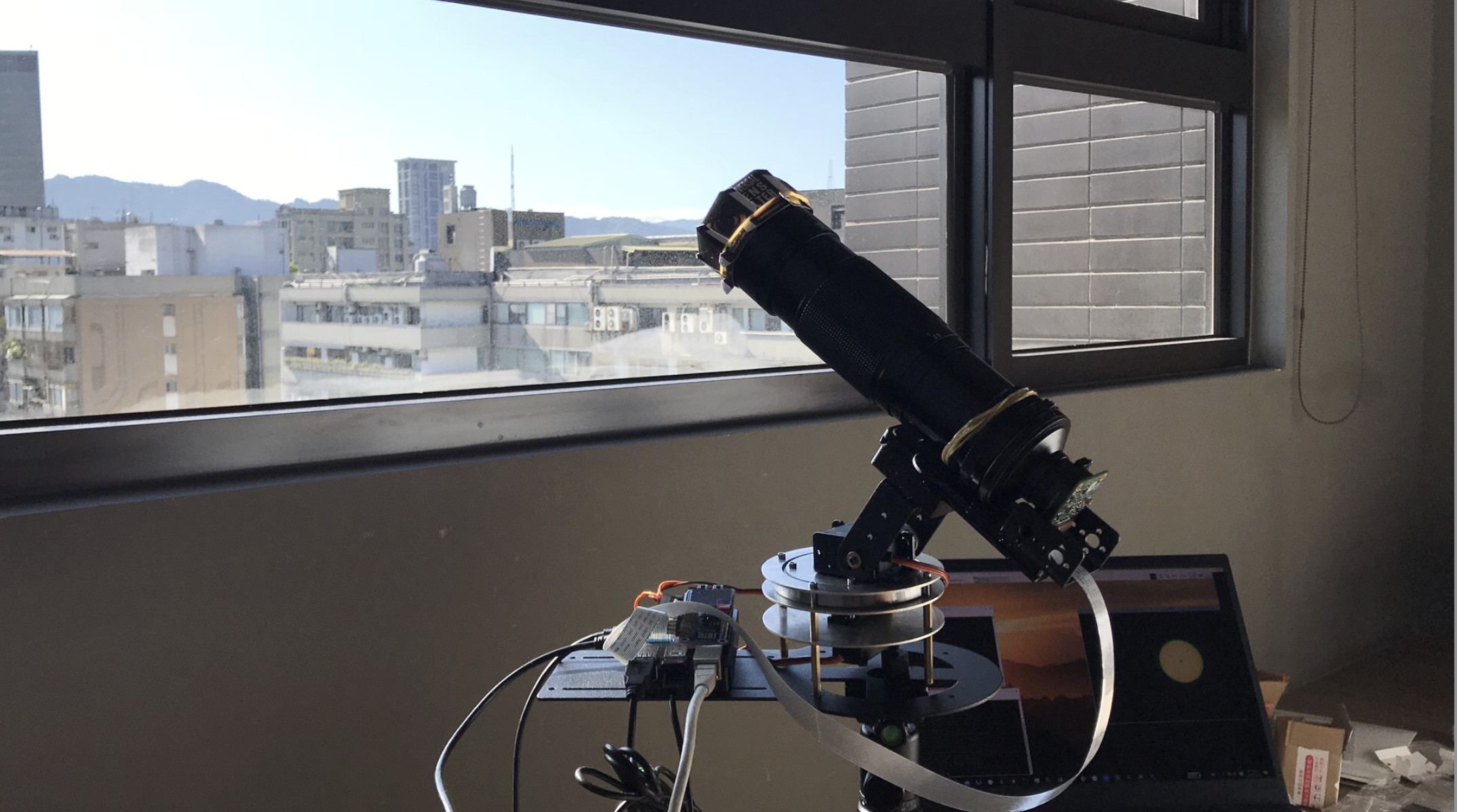
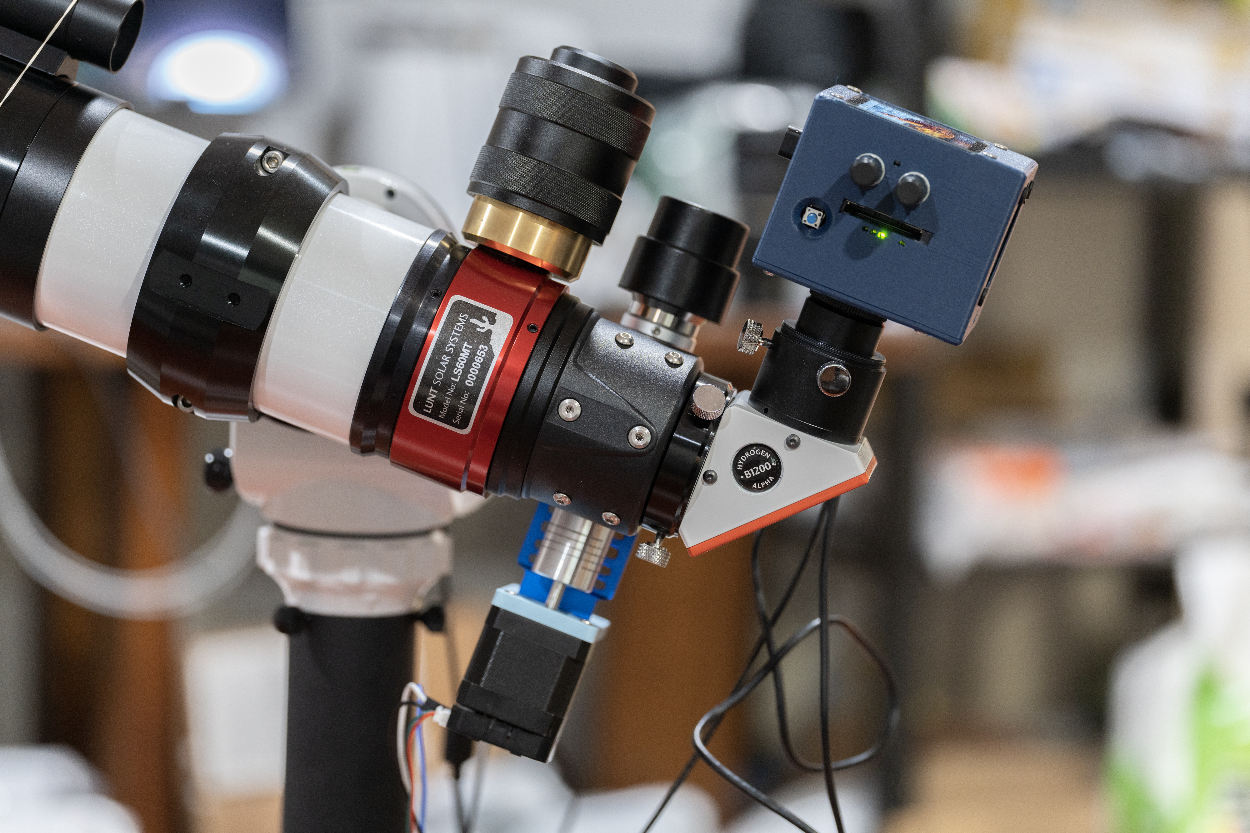
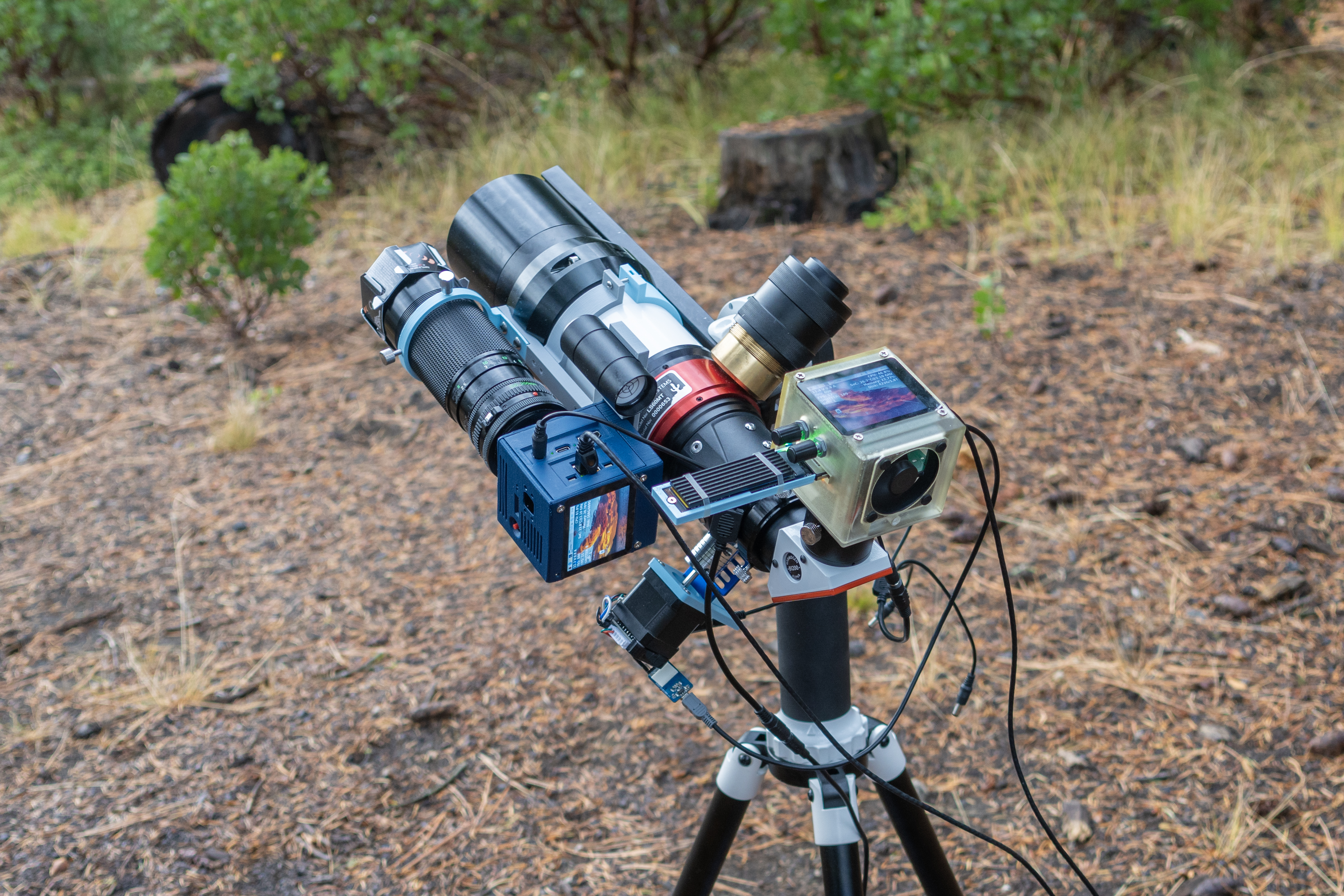
Telescope - LS60MT + 200mm lens
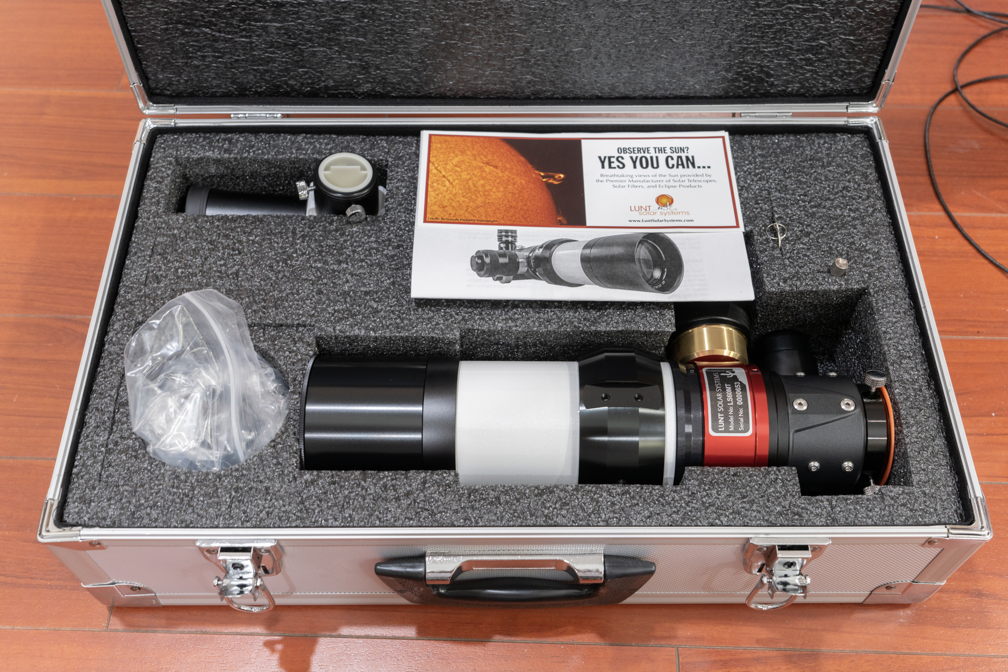
Now, let’s delve into the telescope setup. This time, I’ve opted for a specialized solar telescope from LUNT, the LS60MT.
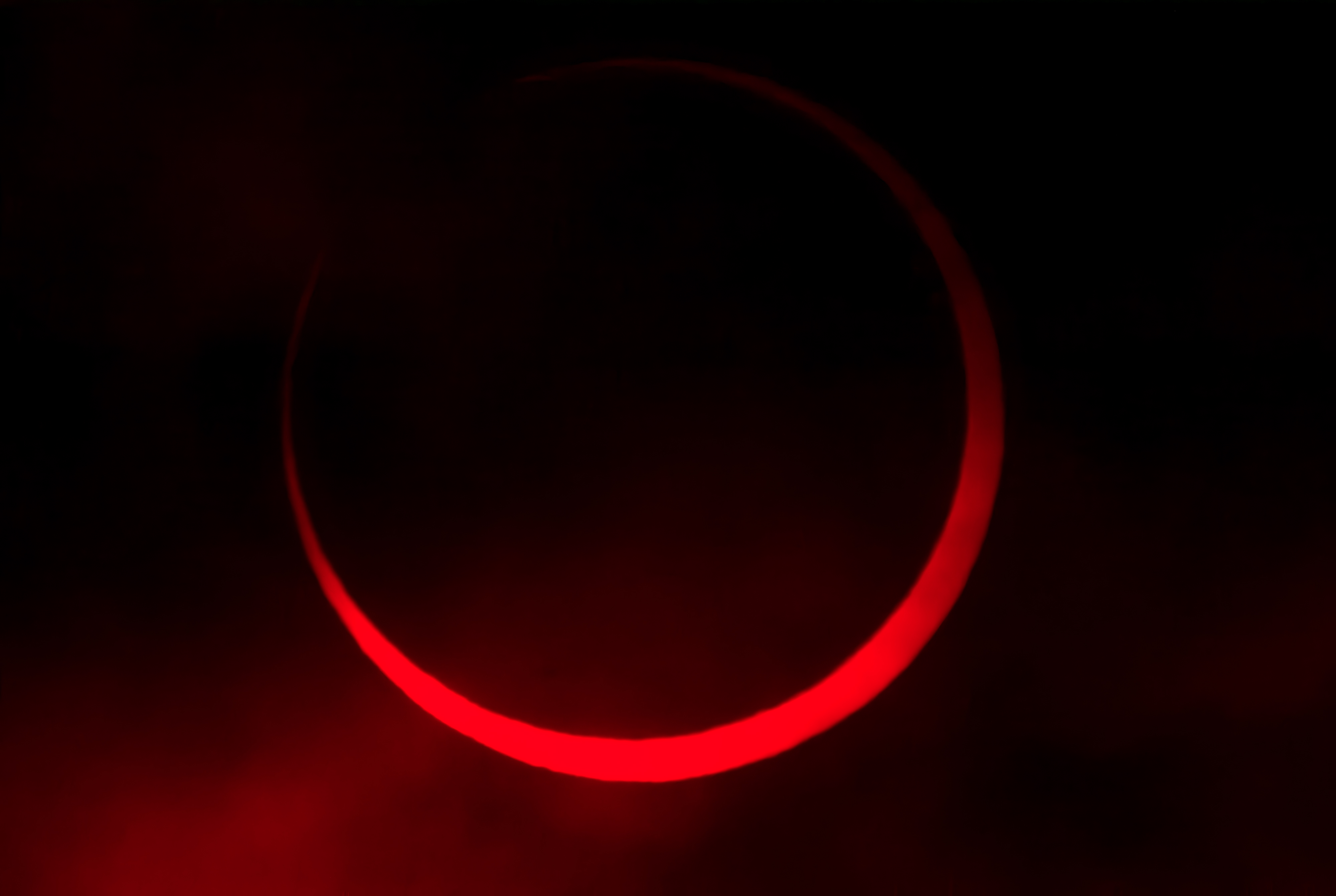
If you compare images taken with solar filters to those from spacecraft like SOHO, you’ll notice that solar filters can only capture sunspots and little else. This is because what you see through the solar filter is the Photosphere, whereas detailed images from the Chromosphere require a specialized filter to isolate the light emitted at a specific wavelength, namely the 656.3nm Hα filter. LUNT specializes in pressure-tunable Hα line filters, and they offer a range of telescopes equipped with this filter.
I chose the LS60MT primarily because it is the most cost-effective option while remaining adaptable for both day and night usage. My main focus is on full-disk imaging, capturing the entire Sun.
Motorized Focus + Challenges with Auto-Focus
Upon receiving the new telescope, I quickly noticed that achieving precise focus was challenging due to the wobbling that occurred when turning the focus knob. To address this, I designed a simple motorized focus mechanism for the telescope, featuring a “smart” stepper motor that can be controlled through a serial UART interface. Additionally, it has an onboard encoder to measure the distance accurately.
Naturally, the next step was to implement auto-focus. However, the reality is that atmospheric turbulence can significantly affect focus measurements. I tried various quantification algorithms to estimate image focus, but the noise caused by atmospheric turbulence often overshadowed the fine-tuning stage. As of now, I rely on manual focus adjustments with a zoomed-in live preview and use keyboard remote focus control.
200mm lens
For solar eclipses, an Hα filter may not be necessary. During a total solar eclipse, you can observe not only the Chromosphere but also the Corona. Therefore, I mounted the 200mm lens I used back in 2020 onto the LS60MT as a secondary white-light camera system, alongside the Starlighteye and another CM4 camera V3.
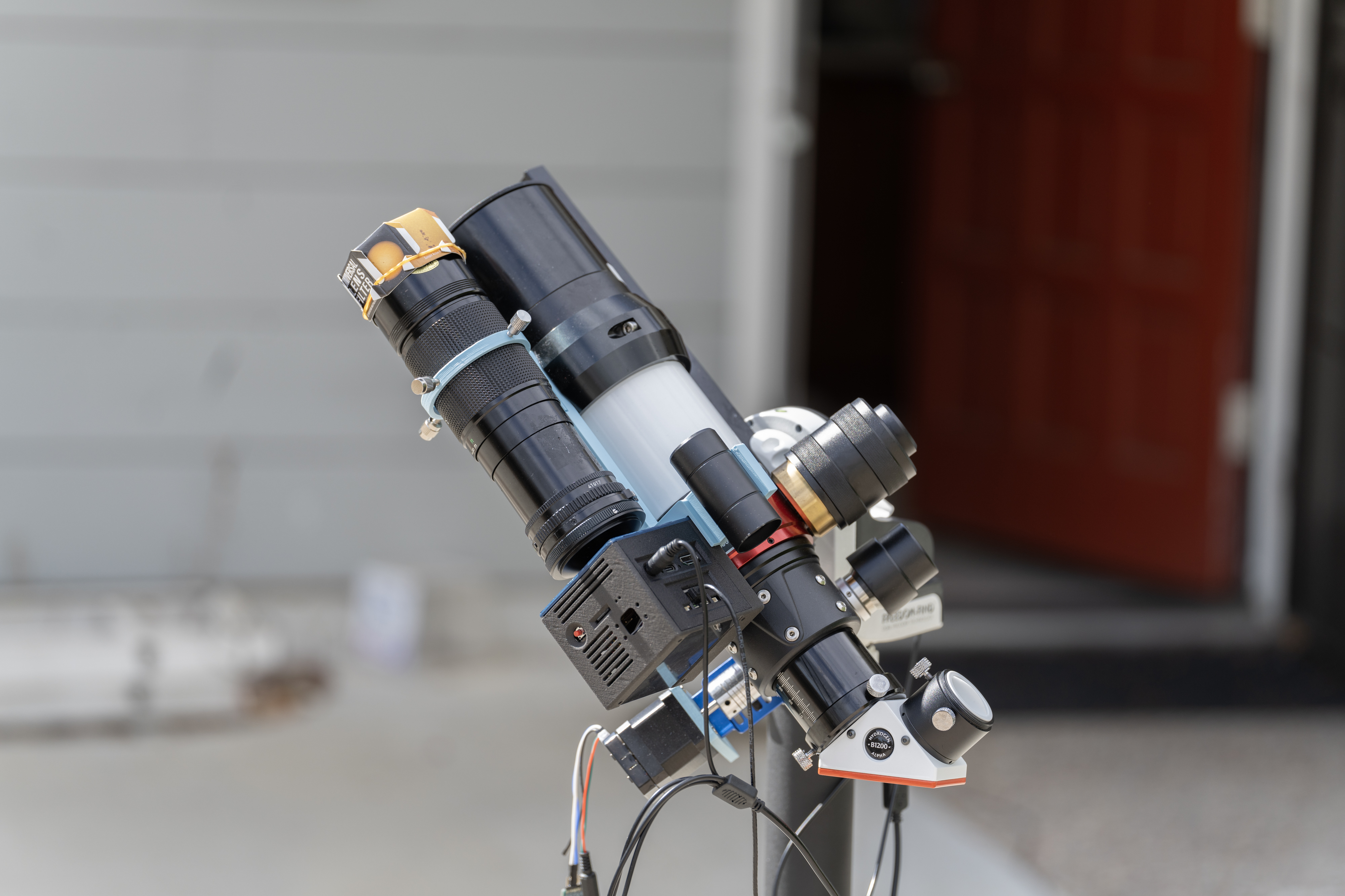
AZ-GTi Mount
With the telescopes and cameras in place, the final piece of the puzzle is the telescope mount. I chose the AZ-GTi Mount from Sky-Watcher. In my experience from 2020, I realized that mount accuracy requirements are quite stringent. Moreover, given that I’m using a 2000+ telescope, opting for an off-the-shelf solution seemed like a wise choice.
Auto Guiding with OpenCV
What makes this mount interesting is that during daylight, it can utilize a one-star alignment process to automatically track the sun. However, the accuracy may not be perfect if your true north isn’t initially aligned correctly. To address this, I use OpenCV to track the solar disk in the preview stream. I can then calculate the origin’s drift and apply correction movements to the mount through the SynScan App.
Post-procesing and test runs - CFA-HDR
Now that we have captured the images, let’s delve into post-processing. One intriguing question arises when working with an Hα filter, which primarily captures red light, while using a color CMOS sensor. What happens in this scenario?
Most CMOS sensors utilize a Bayer color filter array (CFA), which consists of 50% green pixels, 25% red pixels, and 25% blue pixels. When processing the raw image and separating different sub-channels (R, G1, G2, B), you get a resulting image that looks like this:
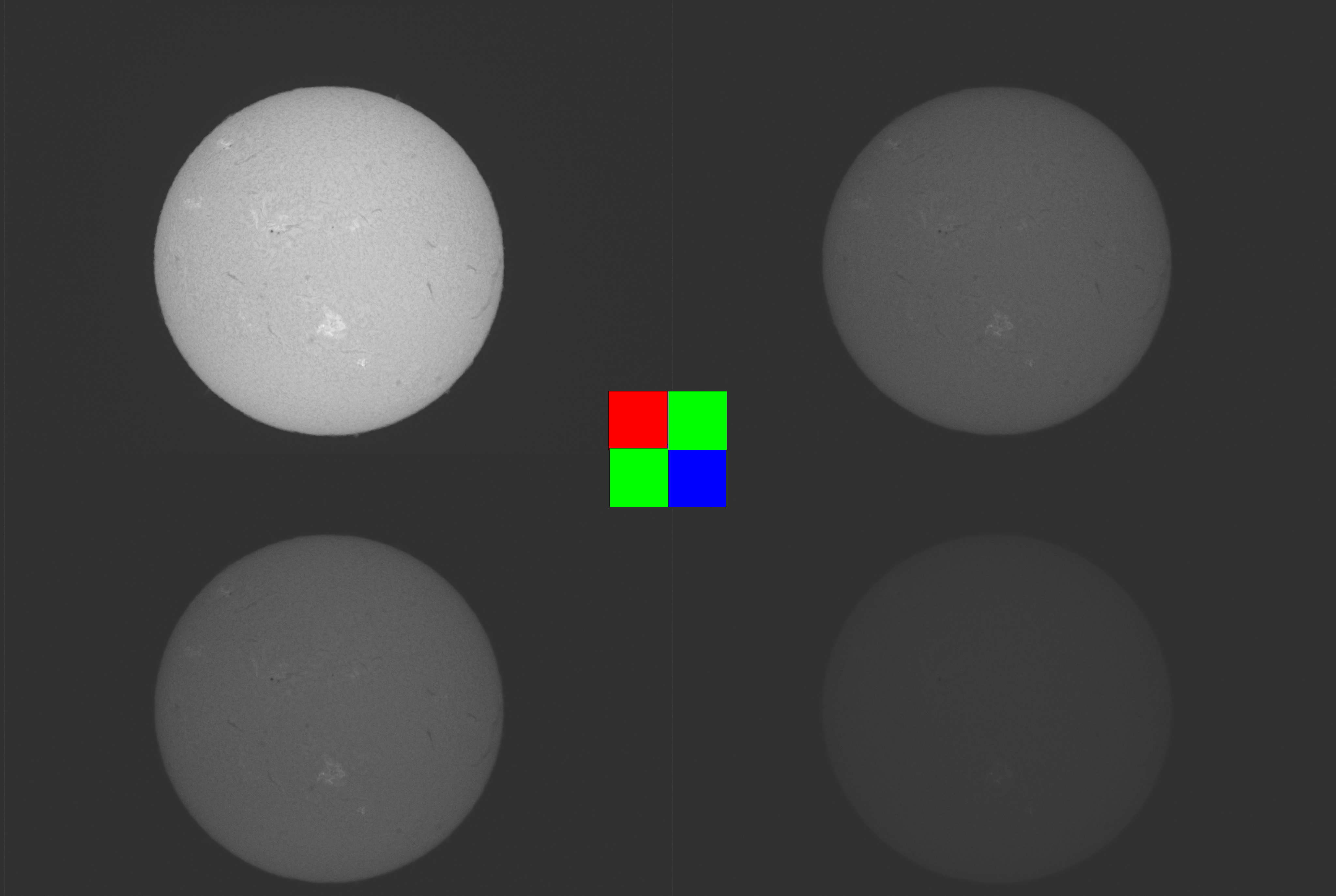
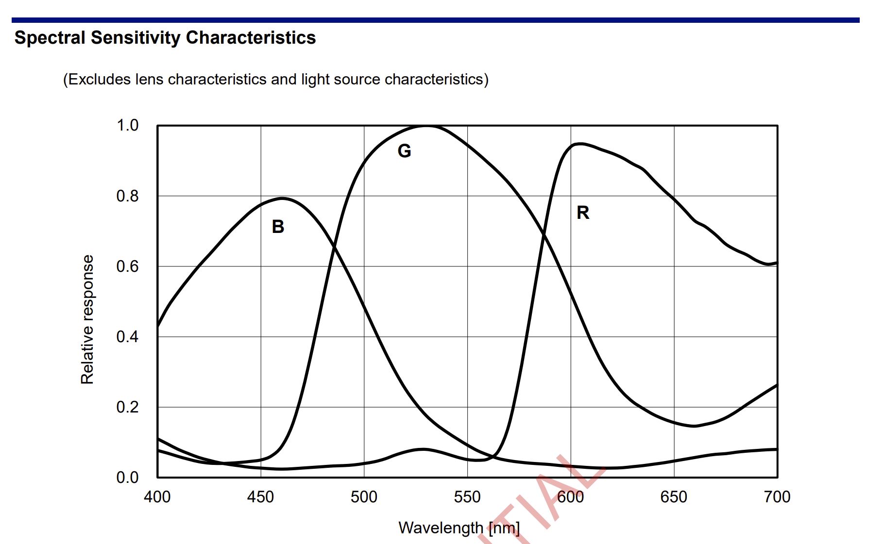
But why do other channels (Green and Blue) also contain data? This is because the CFA filter isn’t as precise as one might think, and green and blue channels experience some crosstalk, as evidenced by the IMX283 spectral sensitivity plot from the datasheet:
The implications for auto exposure (AE) are significant, as AE attempts to increase the green pixel exposure, potentially leading to overexposure in the red channel.
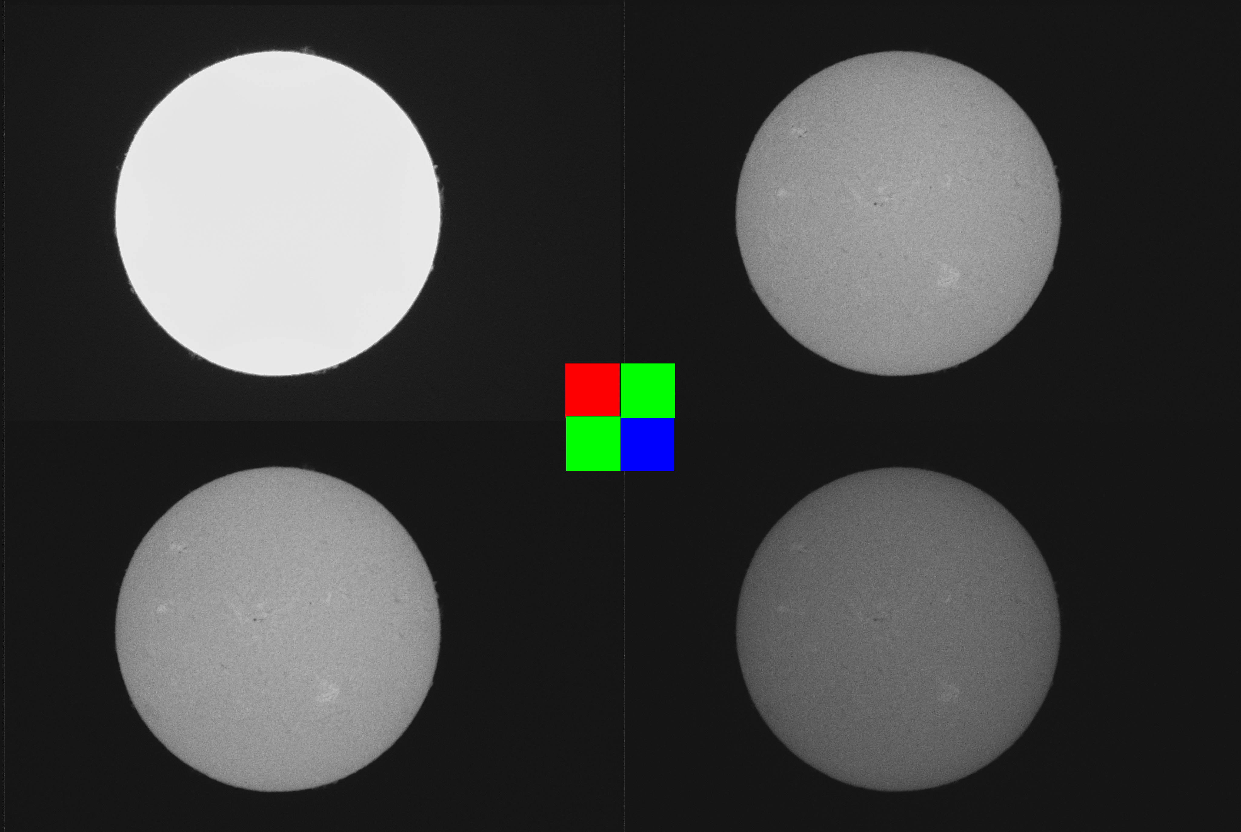
However, upon examining the CFA subchannel plot, it sparked an idea – CFA-HDR (Color Filter Array for High Dynamic Range). This technique leverages the crosstalk to enable long exposure using red channel, normal exposure using green, and short exposure using blue, which are then merged into the final image.
Currently, I’m not employing interpolation, as in debayer algorithms, to maintain the 20MPixel image resolution. Instead, I average the two green channels and directly merge them with the red and blue channels, resulting in 1/4 of the total resolution(5MPixel).
Lucky-Imaging
Despite all these steps, I still need to perform lucky imaging to stack the best parts of each frame. This stacking process is accomplished using AutoStakkert!3.
What’s more is that since lucky imaging requires high speed image capture, my typical capture procedure is to do burst capture in 20FPS for 20 Seconds (fills up my CM4 with 8GB of memory), and then process the resulting 400 frames.
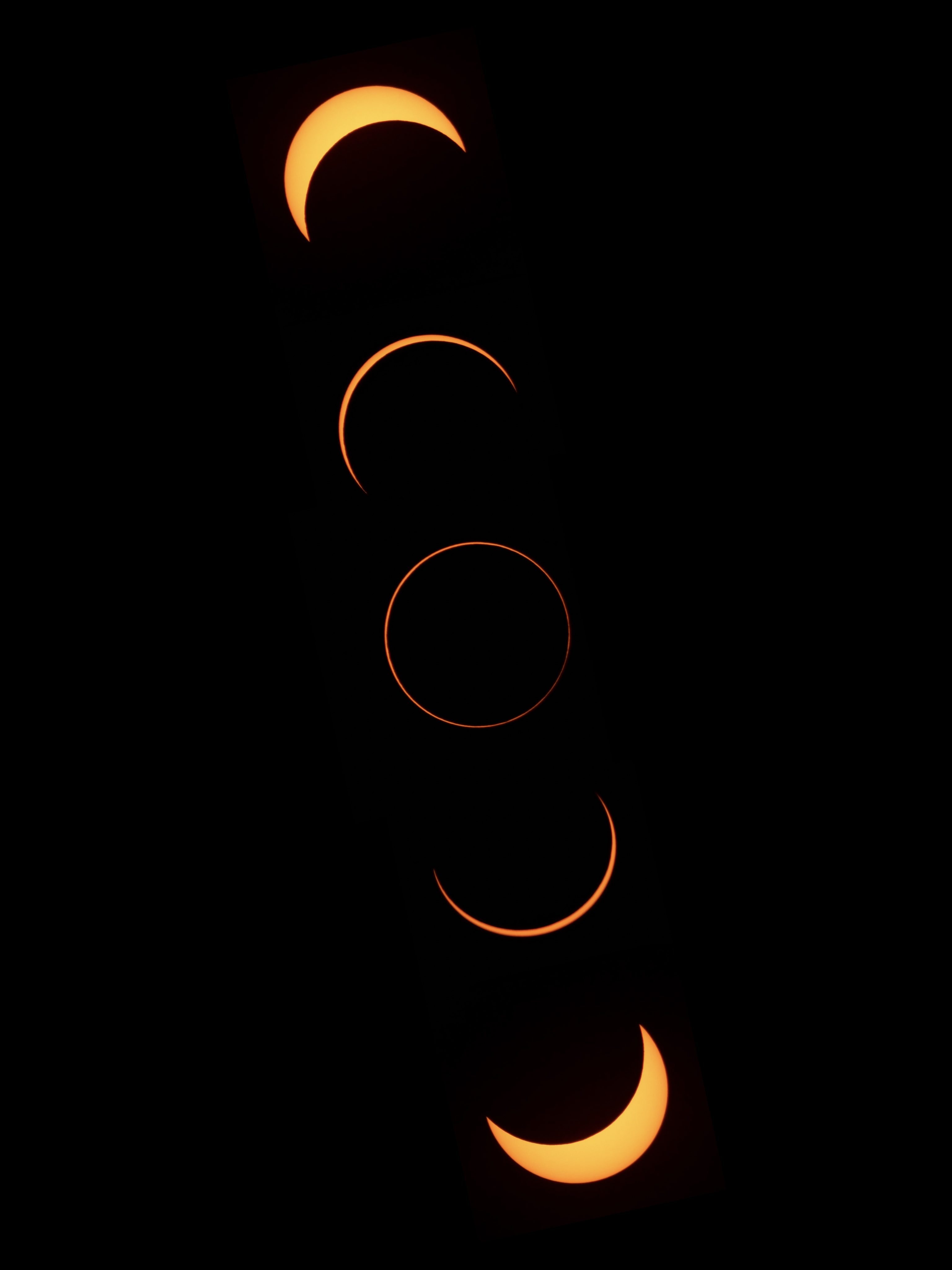
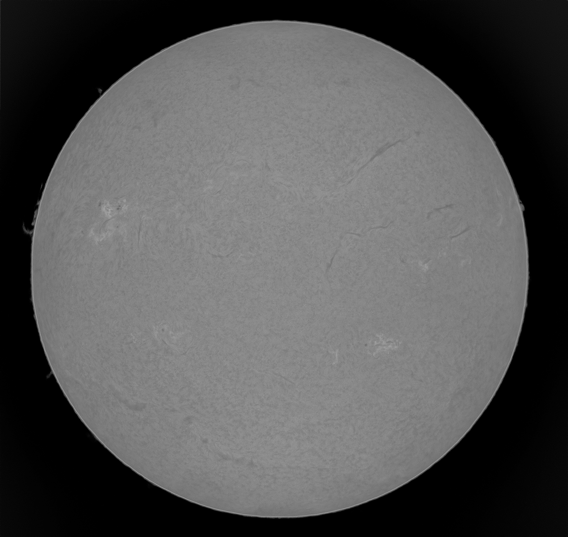
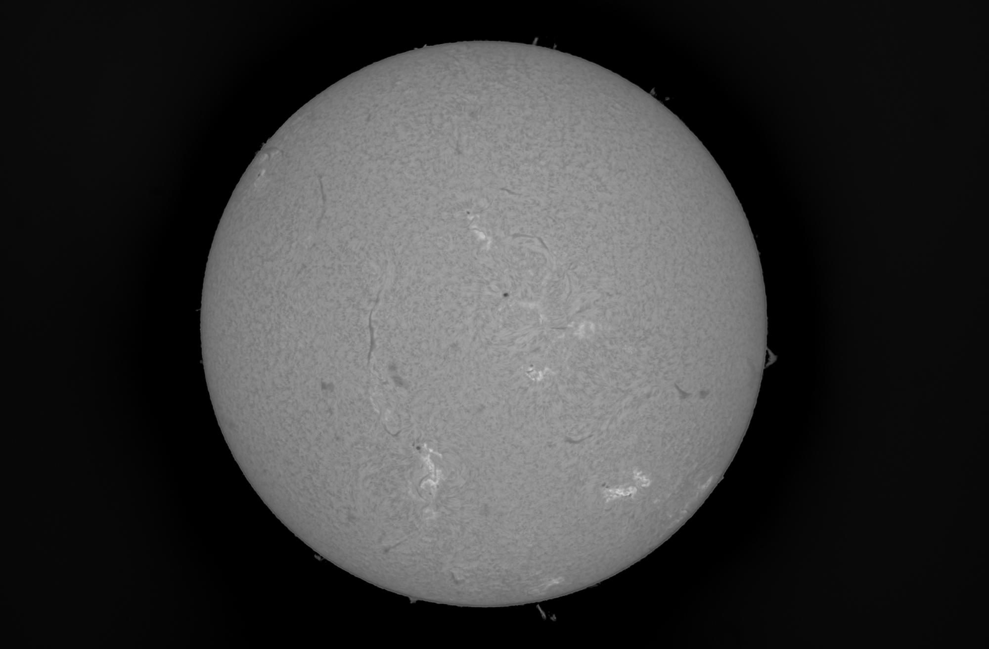
Results
Below, you’ll find some resulting full-disk shots:
Solar eclipse 2023 - Facing the truth of bad weather
The time had come for the much-anticipated solar eclipse on October 14, 2023. I had chosen to observe it from Crescent Lake, Oregon. I stayed at my friend’s house in Corvallis, and together, we embarked on the journey, starting at 6 am in the morning.
We were hopeful that the weather in southwestern Oregon would be favorable, but unfortunately…
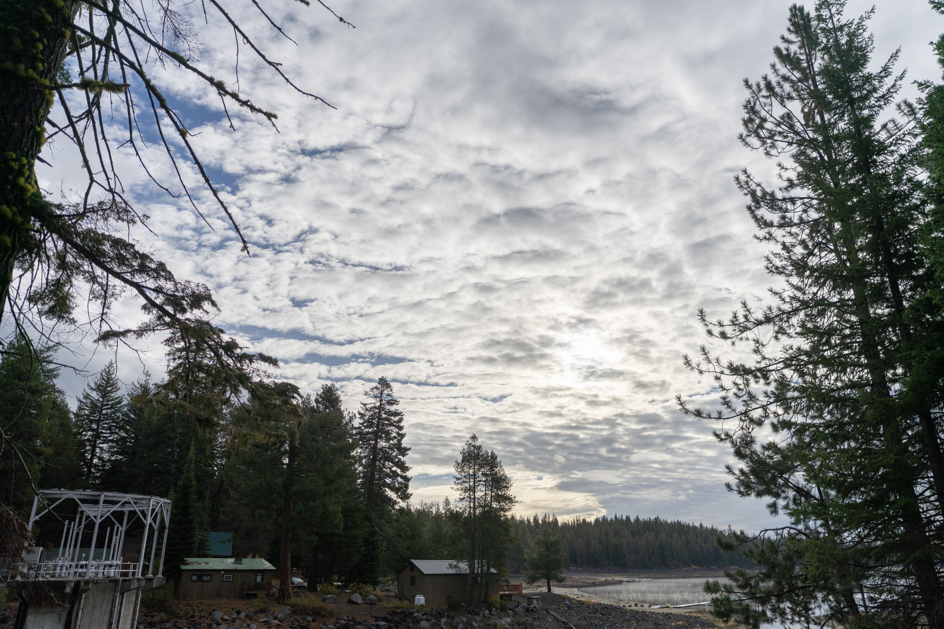
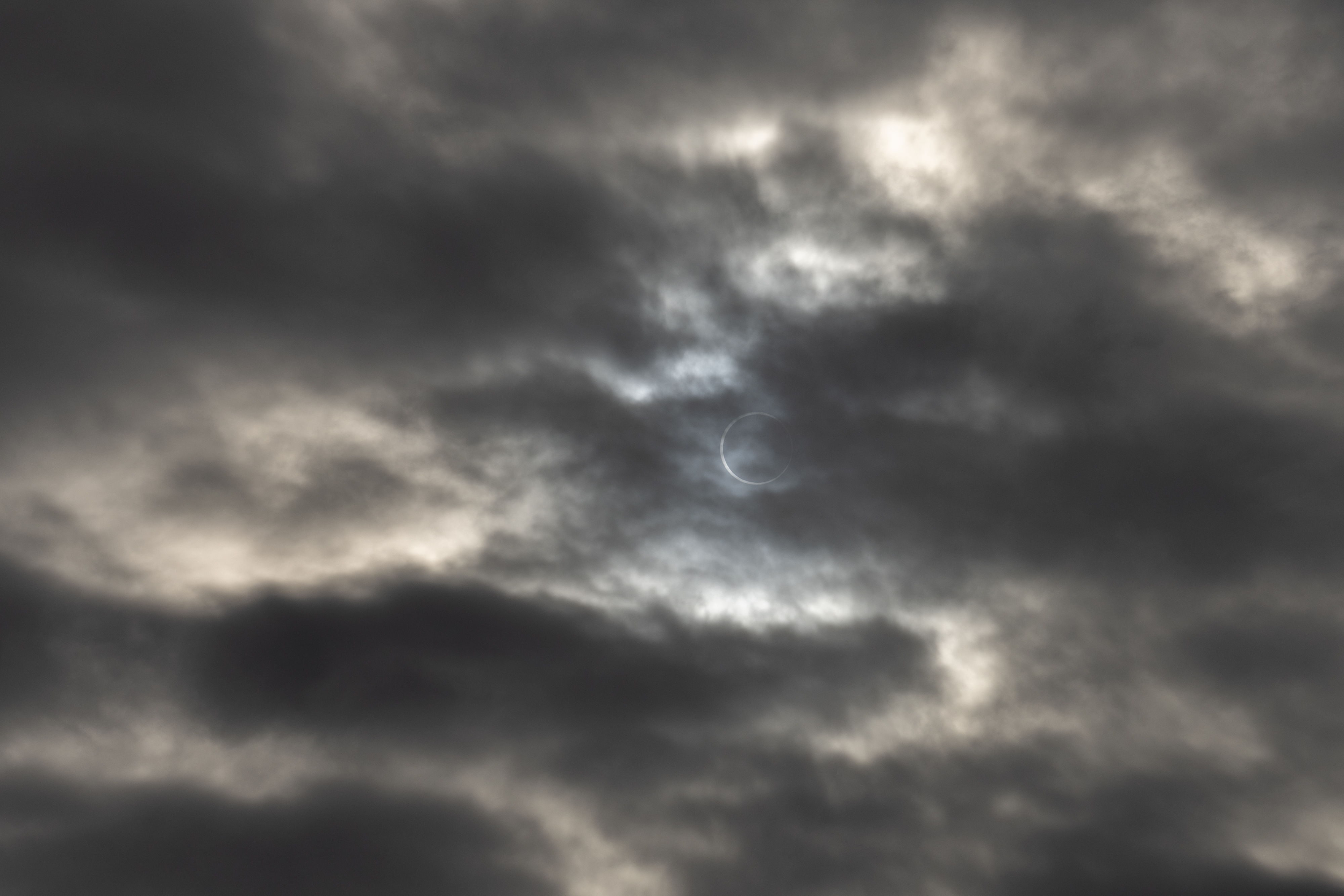
Still, I set up my telescope, holding out hope that I could capture some shots in the brief moments between the passing clouds.
Surprisingly, the 200mm lens proved to be quite useful in assessing the seeing conditions. Here’s a time-lapse video recorded with the secondary camera system, which provided a clear view of the forecast.
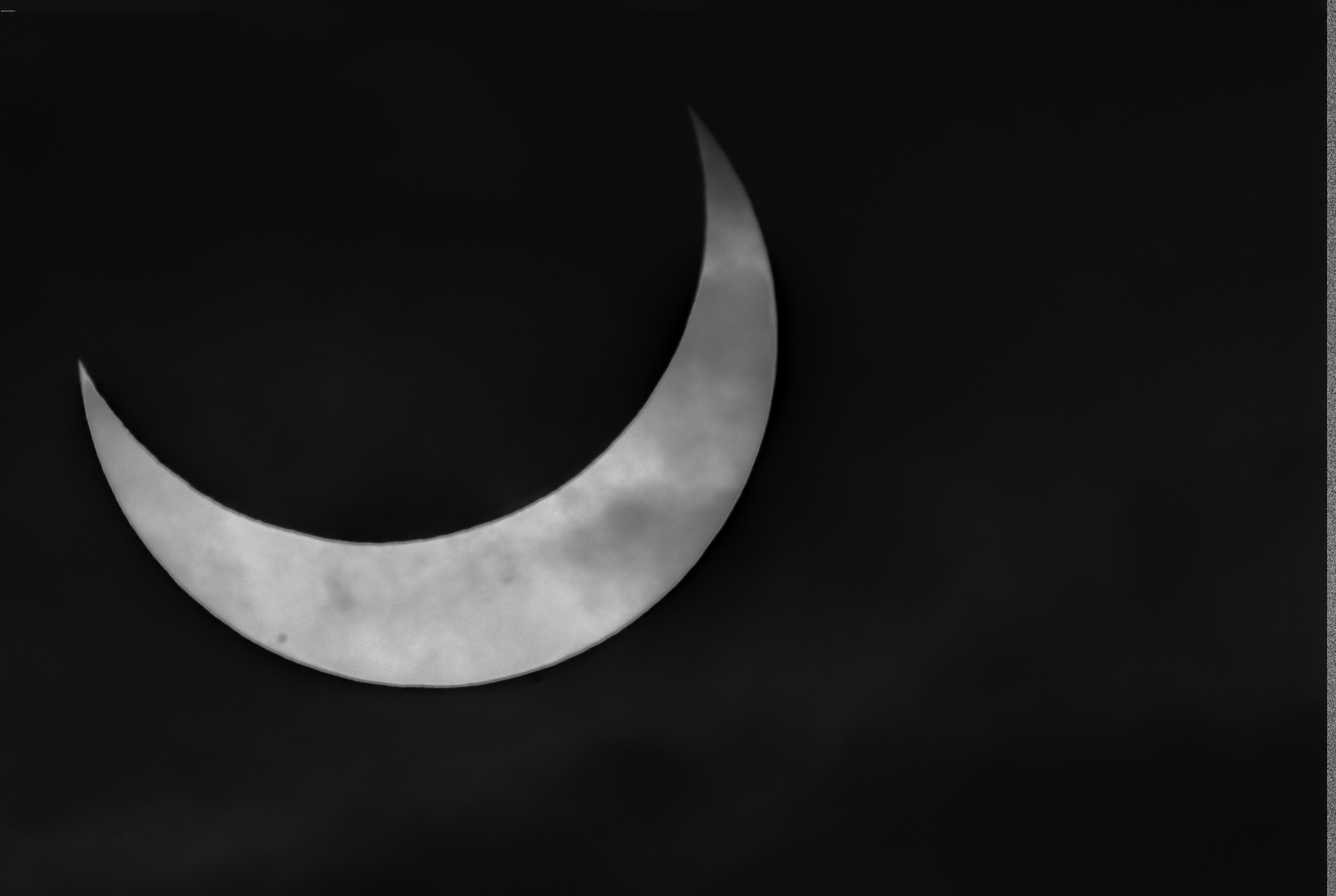
Here is the image/video taken with 200mm lens:
The challenge arose during totality when the clouds covered the sky so densely that the sun can be observed directly with naked eye. Here’s a photo I captured with my A7R4 without any solar filter:
One of the difficulties of dealing with heavy cloud cover was that the motorized focus was not fast enough to do fine-tune focus during the short breaks between clouds. Consequently, I had to resort to manual focus to quickly search for optimal focus.
Moreover, due to the cloud cover, my original plan of using burst capture at 25 FPS for live stacking had to be abandoned. I ended up recording at a slower 12 FPS.
At the same time, the frequent disappearance of the sun behind the clouds meant that I lost the capability to automatically track the sun as planned.
Nonetheless, despite the challenges posed by the weather, I managed to capture some images:
Here is the one taken with main telescope:
Concludion + Future Plans
Raspberry Pi 5
This section is written before I got the RPI5, just FYI
I can already hear the excitement from readers as I type this. Unfortunately, the Raspberry Pi 5 was launched well after my initial planning and the solar eclipse event. What’s surprising about this latest version is that it boasts two onboard 4-lane MIPI interfaces for display and/or camera!
What piques my interest even more is the PCIe 3.0x1 interface on the FPC connector. As highlighted in the disk performance section, the current bottleneck is in disk I/O. Doubling the speed could potentially enable 4K 60FPS raw recording or 20Mpix 20 FPS (reaching the sensor’s limit) without compression. Additionally, the new CPU might allow us to enable some light compression with libtiff to save disk space/bandwidth. The current CM4 just isn’t powerful enough for even simple compression like LZW. However, as of now (October 15), the pinout for the RPI5 hasn’t been released, and I suspect they might have some hidden I2C tricks up their sleeves in that FPC connector, acting as a sideband channel. It would also be interesting to see if it supports hot-plugging on the PCIe port, which could enable me to build a CFE board for RPI5 without additional signaling.
Furthermore, there’s the issue of the FPC connector itself. If you’re familiar with the Small Form Factor, you might have seen A4 ITX-style machines that require a PCIe extender cable to position GPUs on the back of the motherboard. If such extenders are designed for PCIe 3.0, they might not function optimally with PCIe 4.0. Similar to signal integrity issues, I’m quite surprised that they didn’t opt for an FPC with EMI shielding film on the board.
But still, they have said that it is still in the developments, hopefully they have the solution but before that I might just design my own FPC as JLCPCB can do EMI Shielding Film for flex PCB.
Regarding my telescope setup, I might be able to merge both camera systems into one RPI5. One camera’s image stream could be saved to PCIe NVMe, while the other uses the two USB3 ports in parallel to speed up the write process and maximize the available bandwidth of the RPI5. I may need to design a specific HAT for this purpose later.
In general, I’m very excited about the capabilities that the RPI5 offers. Despite its release coinciding with a bad timing for my project and the solar eclipse event, I’m glad it provides the substantial improvements I need.
Concerns About CM5
It might be too early to discuss the Compute Module 5, but I’m noting my concern here. Specifically, I wonder where they’ll place the RP1 on the CM5.
With the current CM4 form factor, there’s simply no space to accommodate the RP1. However, if RP1 is not included on the Compute Module itself, integrating RP1 onto the carrier board doesn’t seem straightforward either (remember, the RPI5 uses a 6-layer PCB stack).
Furthermore, if RP1 isn’t part of the CM5, its pinout may not be compatible with the current CM4 even if the form factor maintains the same.
So, I’m speculating/worried that CM5 might introduce yet another new form factor, potentially requiring many of my current CM4 projects to undergo another round of updates. What’s more, if RP1 isn’t on the Compute Module itself, it would complicate carrier board designs. The only advantage would be the PCIe 2.0x4 lanes (which might even work at PCIe 3.0 speeds because the current limitation is RP1 being PCIe 2.0 only). While the remaining upgrade path for current CM4 might be those CM4-compatiable modules then.
CMOS Sensors - IMX585 Clear HDR
There are some remaining features to enable on the IMX585, specifically the Clear HDR feature. This feature combines two frames in the CMOS sensor directly to produce HDR output. However, I’m still contemplating how to implement those controls in the V4L2 subdevice driver.
500mm Lens
As mentioned earlier, for solar eclipses, white light imaging can also yield interesting results. I have a 500mm FD mount lens for this purpose.
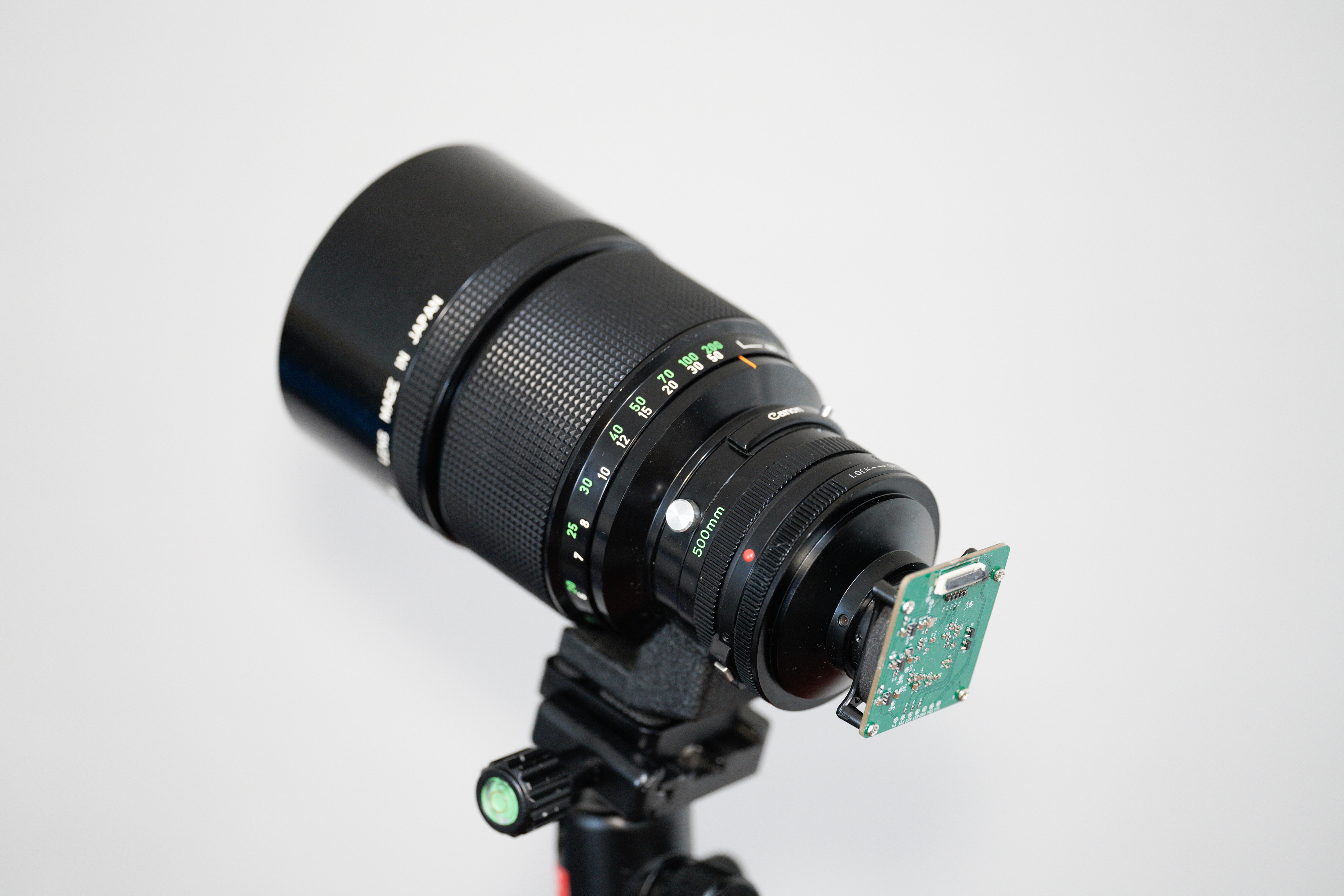
The challenge lies in aligning it with the main telescope. I’ve tried various mounting adapter designs and attached it to the scope, and I can’t get the to align wihtout hacky live adjustment. I’m still planning for a solution, on the same time I also need motorized focusing as well.
Better Camera Mount Process
I must admit that even though I conducted numerous test runs, I didn’t set up the scope from the beginning all the times. With various screws on different parts of the scope, the setup and teardown process was prolonged. This is something I’m aiming to optimize. Additionally, I plan to work on better cable and storage management solutions. What’s more is that the supposedly portable AZ-GTi comes with a large and unwieldy tripod, which makes it hard for me to take it on the plane.
Solar Scintillation Monitor
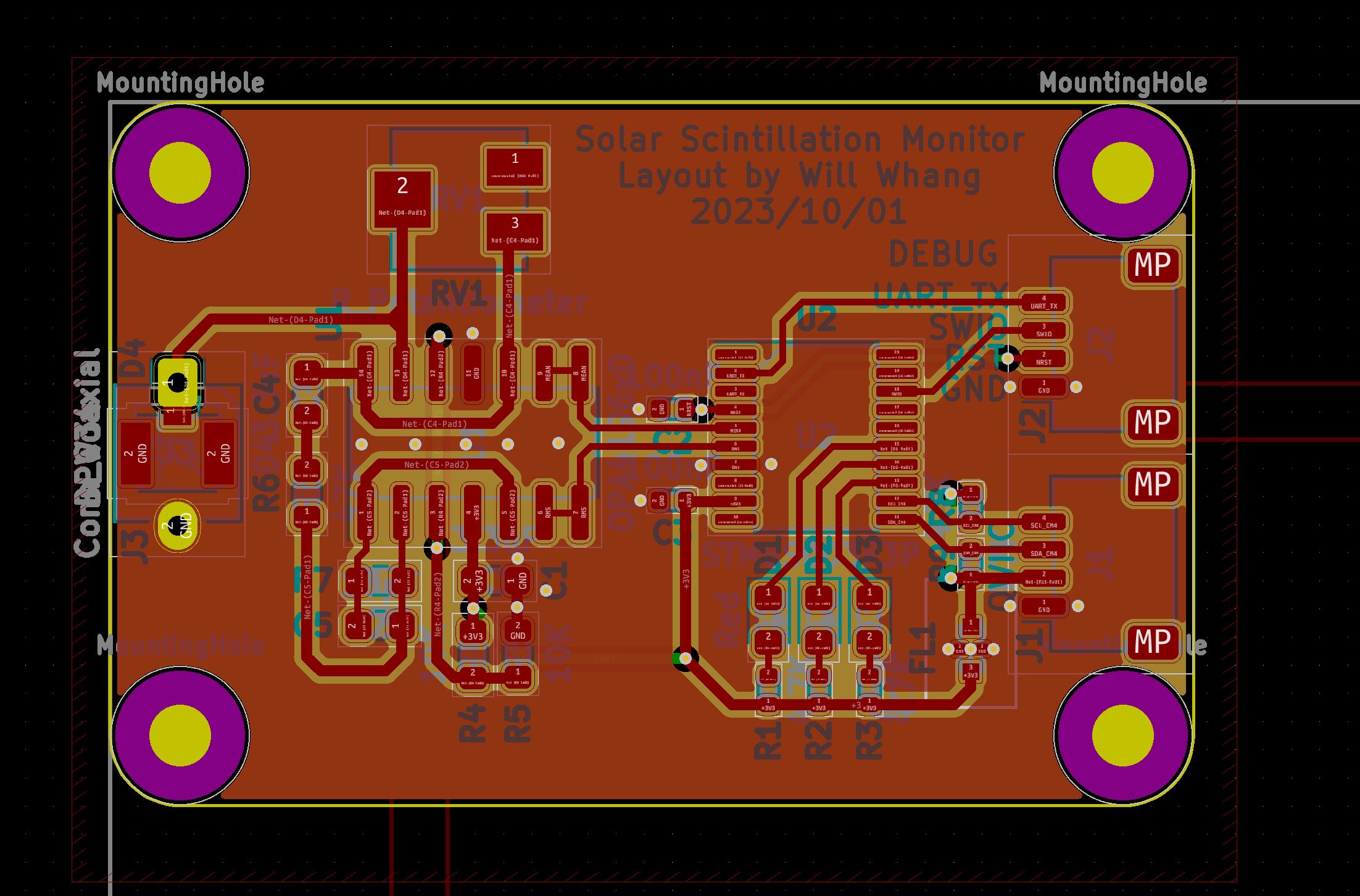
I’m planning to add a Solar Scintillation Monitor to my setup to mitigate the disk IO limitation by only saving the frames during good seeing.
Digital Pressure Controller
Lastly, LUNT telescopes use their pressure-tuned filter, which can be connected to a pump to adjust the pressure digitally link. Turning the stiff pressure knob, similar to manual focusing, causes the wobbling to the scope, and sometimes even shifted the mount. I hope to find a digitalized solution for this also.
Chat-GPT Impact on Coding: The Good and Bad
In 2023, with Chat-GPT available, I heavily relied on it for various coding tasks during my development. It proved to be quite effective for simple, well-defined code generation tasks. While it might struggle with generating large programs, breaking down tasks into smaller steps worked well, similar to how a regular programmer would approach the task. Chat-GPT also had sufficient context memory to remember previous requirements, which was helpful.
However, I often found myself needing to modify the code generated by Chat-GPT. This was usually due to the lack of detailed descriptions I provided to Chat-GPT or because it was faster to add features manually. The challenge was that Chat-GPT couldn’t read my locally modified copy of the code. So, when new features were requested through Chat-GPT, I had to either copy and paste the code back into Chat-GPT or remember the changes and apply them to the newly generated code. This was not the most efficient workflow.
For math-intensive tasks like bit-shifting pixel data, Chat-GPT struggled, even when provided with example code or documentation on NEON intrinsics APIs. It couldn’t effectively handle these tasks.
Overall, Chat-GPT was quite useful for simple coding tasks, such as generating C code to run on CH32V003 to read encoders and buttons. I was more than satisfied with its ability to assist with such miscellaneous coding needs.
Summing Up
Reflecting on my journey from the 2020 solar eclipse to the 2023 event and beyond, I’m quite satisfied with the progress I’ve made over the years. With the help of tools and people from libcamera and CinePi forks, I’ve been able to surpass what I initially envisioned back in 2020. I’m grateful to all the developers who assisted me throughout this journey and patiently addressed my unique questions and challenges.
The results of the 2023 solar eclipse weren’t the best I could achieve, but I’m still grateful that I was able to witness it with my own eyes. For the upcoming 2024 solar eclipse, I plan to conduct more thorough research on the location and carefully plan the trip. I also hope to make necessary upgrades and changes in advance.
Finally, I extend my heartfelt thanks to my high school and undergraduate classmate, Fucent, who drove me throughout the trips and shared in the adventure.
Leave a comment