Solar Eclipse 2024
Solar eclipse 2024
This time around, building upon the foundation of last year’s work, utilizing the Raspberry Pi 5. My aim is to enhance the system’s capabilities and refine our deployment strategies for the 2024 solar eclipse.
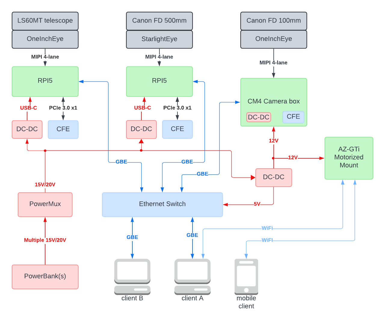
System block diagram
Hardware
Alright, let’s go through each of the main components.
Raspberry Pi 5 Overview
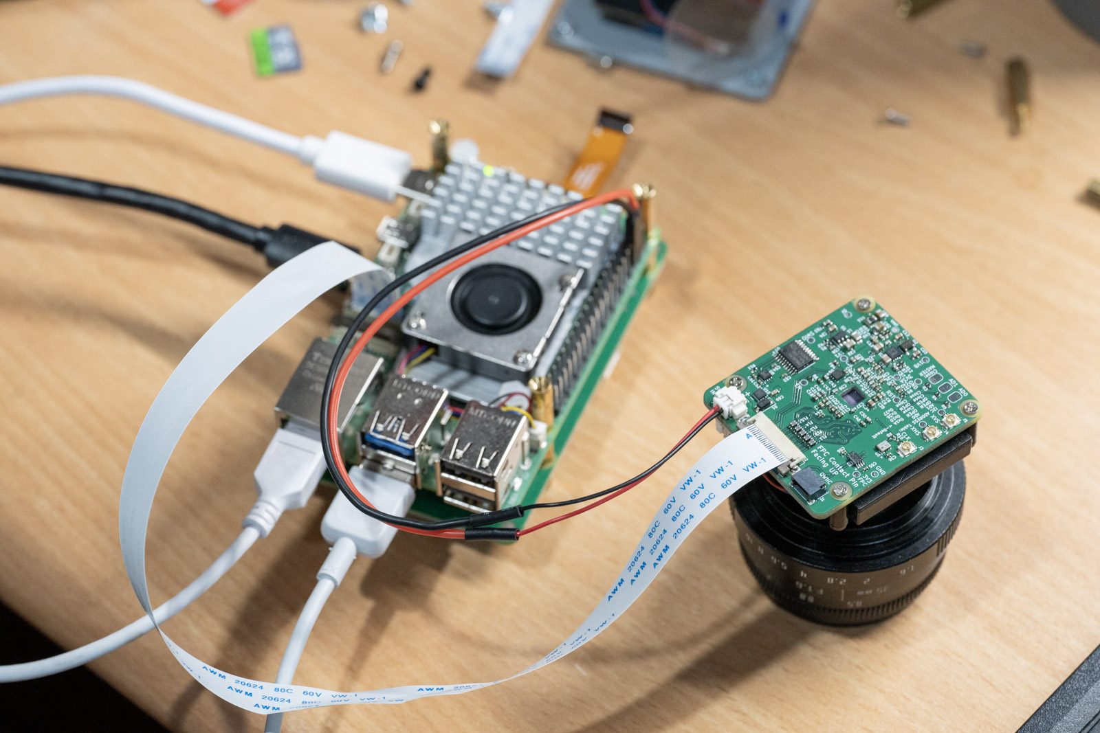
The announcement of the Raspberry Pi 5 just before the 2023 solar eclipse was perfectly timed, that means my main task for this year’s eclipse was to upgrade the core from CM4 to Raspberry Pi 5. Fortunately, the Raspberry Pi 5 includes a 22-pin 4-lane MIPI connector and PCIe FPC, allowing me to directly connect my camera module and CFexpress card. This eliminated the need waiting for CM5 and saved me from having to build a custom base board.
While many people focus on the Raspberry Pi 5’s CPU performance and the RP1 “southbridge”, for me, the most significant change and challenge is the new PiSP Camera ISP. The features of the PiSP, such as enhanced ISP performance and HDR processing, have me very excited. I eagerly anticipate connecting my camera modules to the Raspberry Pi 5. An interesting tidbit: the announcement of the Raspberry Pi 5 was leaked by a review + RS’s Ad. One of the site released the information a few hours early, and I stayed up all night to catch the start of preorders.
Watching the announcement podcast? discussing the PiSP features, I couldn’t wait to experiment with my camera modules on the new Raspberry Pi 5.
OneInchEye + StarlightEye on PiSP
Having had the Raspberry Pi 5 for about six months now, it’s time to delve into the real-world experiences and the nitty-gritty of the setup.
The setup process was incredibly smooth, essentially unchanged from previous models. I used the same drivers and even the same devicetree overlays, allowing the Raspberry Pi 5 to recognize my camera module. However, integrating Libcamera’s support for the new PiSP required some file reorganization due to the dual ISP architecture—VC4 and PiSP—necessitating additional folders. Moreover, the new PiSP requires updated tuning files, though I initially tried using an uncalibrated one just to see if it would work at all. Once I managed all the necessary adjustments, I was able to open the camera apps and was greeted by this successful preview:
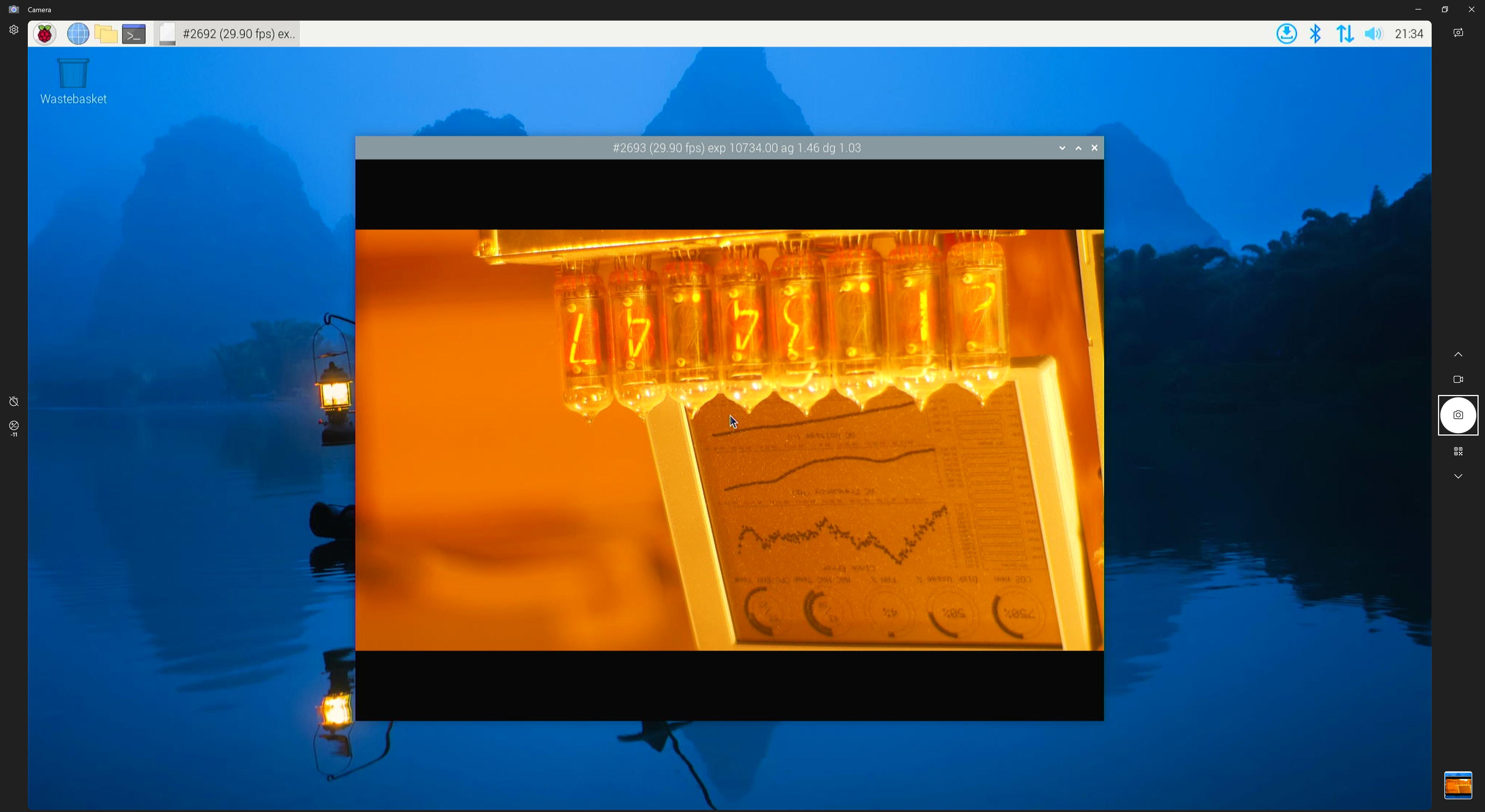
It was quite astonishing to see it work so well on a different ISP structure. The image above shows the StarlightEye (IMX585) with ClearHDR enabled, capping the framerate at 4K 30p. Next, I decided to disable ClearHDR in the driver to test the 4K 60p setting:
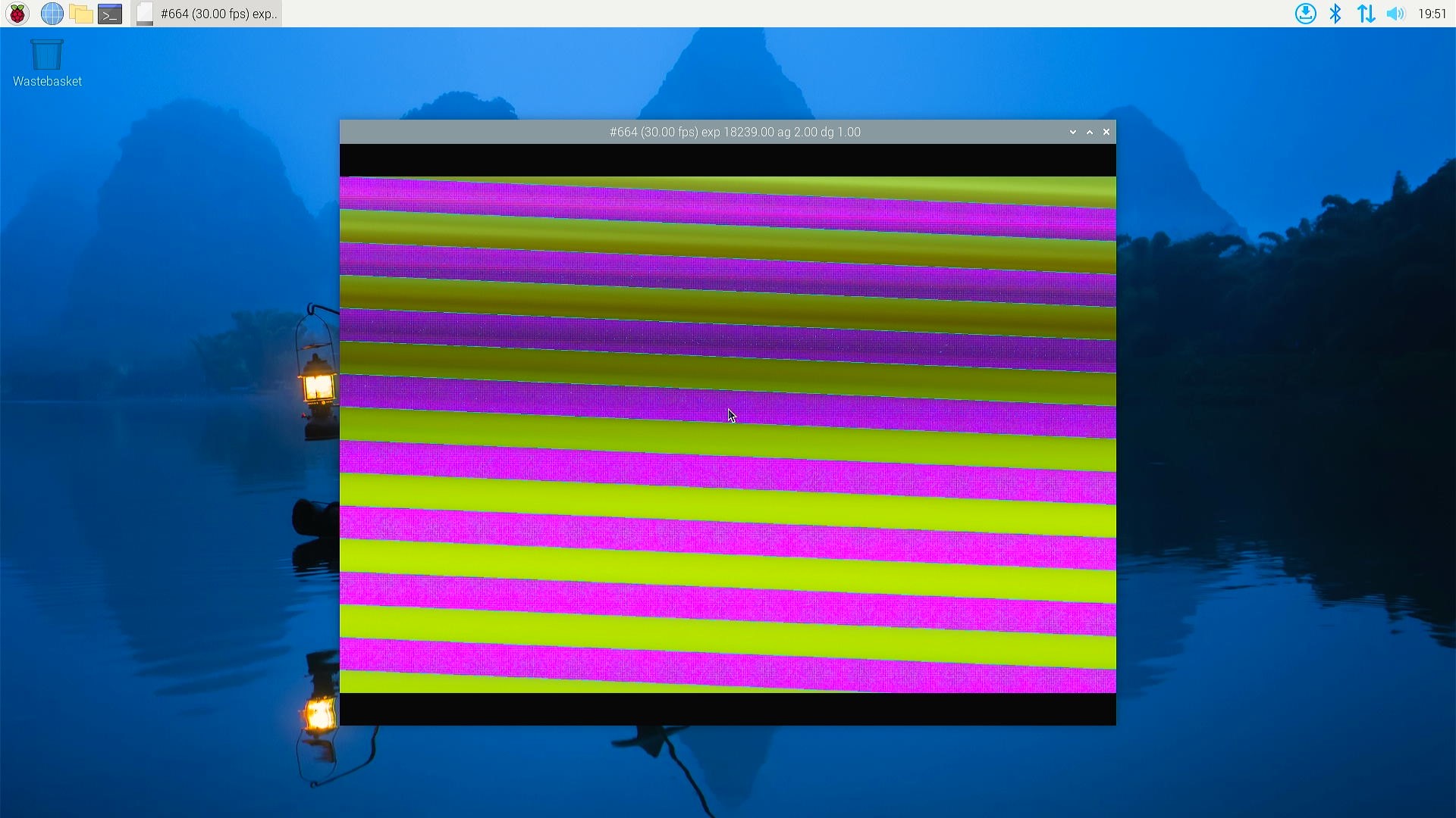
Unfortunately, that’s where issues started to appear. The challenge is that there is no straightforward way to debug this. The MIPI link speed is consistent, and since ClearHDR works by reading the same column twice at two different gains and combining them on the sensor, it shouldn’t have been corrupting the frame.
With the assistance from the Raspberry Pi forum and the Libcamera community, I discovered that I had overlooked a key limitation of the PiSP - a throughput of 400Mpix/s for the Camera Front End (PiSP-CFE). Doing the math, this translates to a frame rate limit of about 4K 45 FPS.
The PiSP isn’t just a monolithic block inside the SoC but is divided into two sections: the Frontend in the RP1 and the Backend in BCM2712. The Frontend, which performs the initial frame processing and can apply an optional 8-bit compression, sends the data and stats to the Backend. Notably, the Frontend’s clock is independent of the GPU clock, which differs from predecessors like the VideoCore4 in the CM4. Even though the RP1 datasheet states that the PiSP-CFE can reach up to 700Mhz, in practice, it is set to 200Mhz. With a two pixel per clock limit, this sets a throughput cap of 400Mpix/s. The RP1’s MIPI receiver supports up to 1.5Gbps per lane, which, with a 4-lane configuration, can easily exceed this limit. Additionally, since this subsystem is in the RP1, overclocking isn’t supported through the config.txt as it is with the GPU and CPU clocks.
Overclocking the RP1 for Enhanced PiSP Performance
Despite some initial hurdles with achieving 4K 60 FPS on my Raspberry Pi 5, with the help from Kieran Bingham and ideasonboard. There is a way to overclock the RP1, enhancing the PiSP performance. As with any overclocking procedure, this method carries risks and is not officially recommended by Raspberry Pi.
One of the reasons this is not recommended by Raspberry Pi is due to the potential risks involved in overclocking. We are not directly overclocking the PiSP-CFE but adjusting the system clock on the RP1. This could potentially lead to instability or damage if not handled carefully.
Here’s the step-by-step process I followed to overclock the RP1:
- Modify the Device Tree Source: edited the file
./arch/arm/boot/dts/broadcom/rp1.dtsi. Specifically, changeRP1_PLL_SYSandRP1_CLK_SYSto<300000000>. - Recompile and Install the Kernel: After making the changes, recompiled the kernel to apply these new settings.
- Update Libcamera Configuration: In the Libcamera directory, modify
./src/ipa/rpi/controller/controller.cpp. Under the “pisp” section, change:
.minPixelProcessingTime = 1.0us / 380
to
.minPixelProcessingTime = 1.0us / 580. - Recompile and Install Libcamera: After updating the settings, recompile and reinstalle Libcamera to ensure the changes were implemented.
By cautiously overclocking just +100Mhz higher than the default, I managed to enhance the ISP’s power sufficiently to support 4K 60 FPS, finally achieving the desired performance level.
As for the OneInchEye (IMX283) on RPI5, it all thanks to the invaluable assistance of Kieran Bingham again and the team at Ideas on Board, IMX283 sensor now functions flawlessly on the Raspberry Pi 5. Initially, I encountered similar issues with the IMX283 as I did with the IMX585—specifically, broken frames. Despite reducing the frame rate, the frames remained corrupted, which I suspect was due to PiSP’s sensitivity to frame dimensions. Unlike its predecessors, where a slight mismatch in frame dimensions might result in a blank or cropped image, PiSP would display corrupted frames.
Kieran Bingham dedicated substantial effort to pinpoint the correct dimensions and offsets, resulting in perfectly functioning images. Thanks to the team’s work (Umang (@uajain@fosstodon.org) and Kieran Bingham), the IMX283 driver is slated to be upstreamed to kernel v6.10, greatly benefiting the opensource community.
Here is the capability currently looks like - with overclocked RP1 of course!
pi@RPI5test:~ $ rpicam-still --list-cameras
Available cameras
-----------------
0 : imx283 [5472x3648 12-bit RGGB] (/base/axi/pcie@120000/rp1/i2c@80000/imx283@1a)
    Modes: 'SRGGB10_CSI2P' : 5568x3094 [30.17 fps - (0, 285)/5472x3078 crop]
                             5568x3664 [25.48 fps - (0, 0)/5472x3648 crop]
           'SRGGB12_CSI2P' : 2784x1828 [51.80 fps - (0, 0)/5472x3648 crop]
                             5568x3664 [21.40 fps - (0, 0)/5472x3648 crop]
Transitioning back to the IMX585, I had to confront a significant challenge concerning its power supply requirements on Raspberry Pi5. The IMX585 requires three different power rails: 3.3V analog, 1.2V and 1.8V digital. The Raspberry Pi’s 22-pin FPC connector, which supports 4-lane MIPI, offers only a single 3.3V power supply pin. If I use the original designed I put in my CM4 camera box, because the 3.3V input being used as a 3.3V analog through only a ferrite bead, on RPI5 for some reason will have increased noise that impact the image quality. Here is a great write down of the issue from robertimorrison, I have observed the exact same behavior. Initially, I attempted to use a step-up converter to elevate the 3.3V to 5V for the onboard IR filter switch driver, followed by a 3.3V LDO for a clean analog power supply. However, this setup led to excessive voltage drop on the 5V rail when the camera powered up, as the FPC’s cable resistance could not sustain the necessary voltage levels for step-up converter to function.
Ultimately, I have to design the StarlightEye board to require an external 5V power supply alongside the FPC to function correctly. This is not ideal but I’ve tried.
Here is the capability currently looks like - also with overclocked RP1. Notes that the 16bit format is with the ClearHDR mode enabled, will talk slightly more on that later.
pi@RPI5test:~ $ rpicam-still --list-cameras
Available cameras
-----------------
0 : imx585 [3840x2160 16-bit RGGB] (/base/axi/pcie@120000/rp1/i2c@80000/imx585@1a)
    Modes: 'SRGGB12_CSI2P' : 1928x1090 [90.17 fps - (0, 0)/3840x2160 crop]
                             3856x2180 [60.00 fps - (0, 0)/3840x2160 crop]
           'SRGGB16' : 1928x1090 [30.00 fps - (0, 0)/3840x2160 crop]
                       3856x2180 [30.00 fps - (0, 0)/3840x2160 crop]
Next, I’ll explore how are we the processing the frames, which I will cover more extensively in the CinePi section. Now, let’s turn our attention to storage solutions.
CFE Hat: Bringing CFExpress to Raspberry Pi 5
Introduction of PCIe 3.0
The Raspberry Pi 5 brought with it an exciting upgrade: PCIe 3.0. This was a significant leap from the PCIe 2.0 x1 with 400Mb/s disk bandwidth, which had been a major bottleneck as noted in my previous eclipse post. With PCIe 3.0 x1 now available, and notably on a standard 16-pin FPC connector without needing a Compute Module, the possibilities for storage expansion and speed were immediately evident.
Developing the CFE Hat
Upon the announcement, I quickly opened my KiCad project to start adapting my CFexpress card circuit for a new project dubbed the CFE hat. However, I hit an early snag—the pinout wasn’t published yet. In the early days following the RPI5 release, I wasn’t in a rush to build the board, given the numerous questions surrounding the PiSP and other priorities. However, community members like @m1geo and @Mirko_DIY quickly deciphered the pinout even before the official documents were released by Raspberry Pi. This early work also led to Pineboards’s success by creating a wide range of M.2 Hats, which became almost essential for RPI5 users.
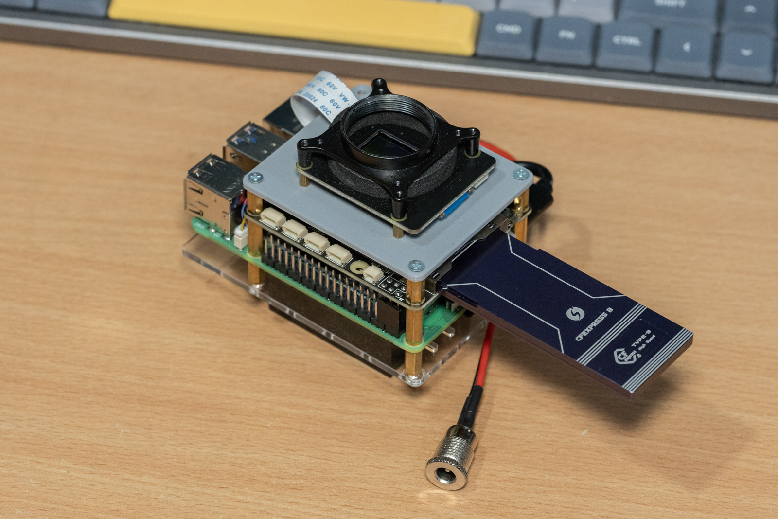
With the community findings, I was able to finalize and get the CFE board operational. You can see the design and further details on my GitHub.

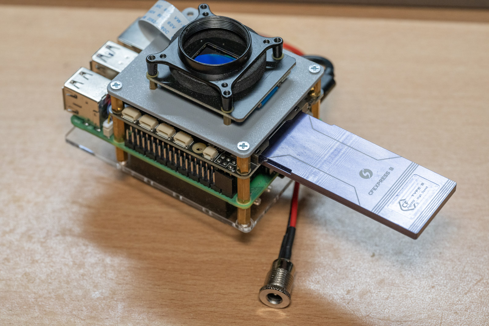
The board is versatile, designed to be mounted either on the top or bottom of the RPI5. Notably, the CFexpress Cards I used are DIY-built with NVMe SSDs, and there’s even an M.2 2280 to CFexpress adapter available.
Overcoming FPC Connector Challenges
My initial assumptions about the 16-pin FPC were that it would include I2C pins, PCIe CLK request and Reset, two 5V pins, with the remainder for GND and PCIe clock/TX/RX. I hoped to use I2C on the FPC to handle card insert and eject signals for automounting and manual unmount via a button press. However, despite the indications in the overlay file, these I2C pins were absent in the official FPC documents, leading me to incorporate a QWIIC port for I2C communication.
The onboard MCU, CH32V003, acts as a simple I2C to GPIO converter. It also reads the enable signals from the PCIe FPC to power the CFE card on and off. The software handles the GPIO states to detect card insertion and mount it or detect the eject button press to unmount the card while driving the LEDs on the hat to indicate status.
Video Demonstration
Here’s how the board functions in action, showing a new disk being mounted automatically and unmounted via a button press on the hat:
The Challenge with FPC Cables
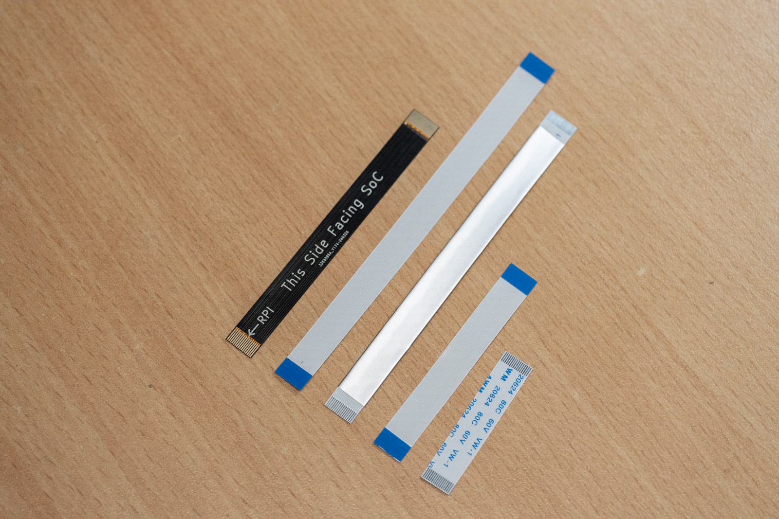
A significant realization was the limitation of common FPC cables in passing PCIe 3.0 signals, effective only up to about 3 cm. Aluminum-covered FPCs performed even worse, failing to complete link training. Consequently, needing an 8 cm cable to mount the board flexibly (Both top and bottom mountable), I had to design the FPC myself.
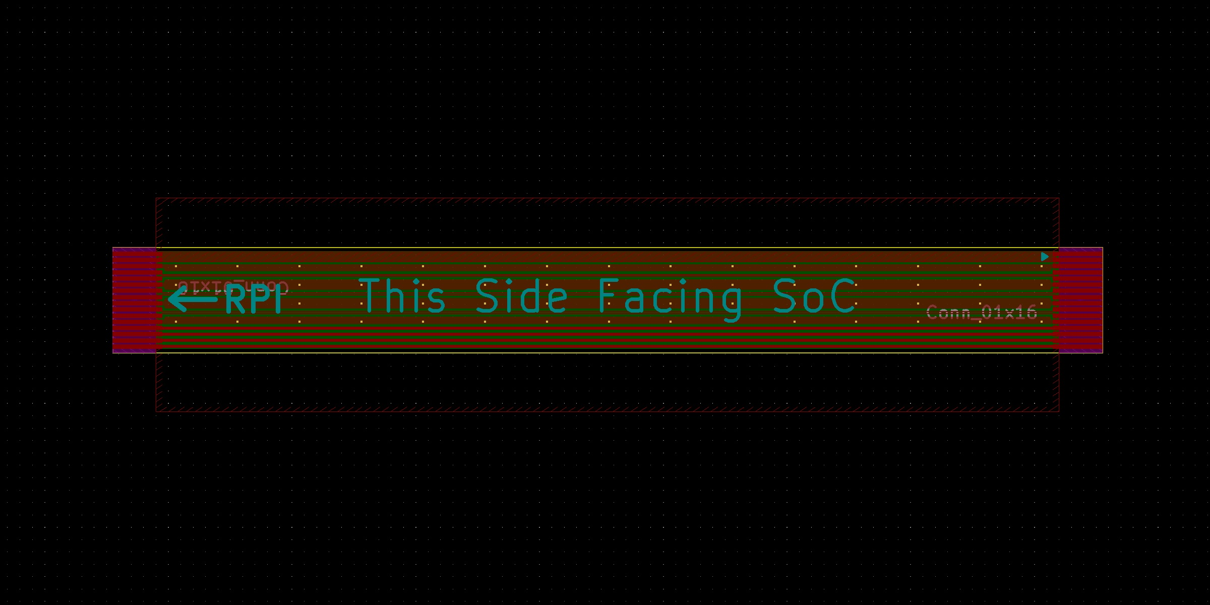
When developing the custom FPC for the CFE Hat, I encountered some complexities that extended beyond just the typical PCB file requirements. These included specifying the dimensions for stiffeners and the grounding contact for the black EMI filter cover. Navigating these details in KiCad proved challenging, as there wasn’t a straightforward way to include these specifications.
Thankfully, the engineers at JLCPCB were instrumental in this process. They applied their standard FPC specifications to the project. An interesting point to note is that the traces on the FPC ended up being smaller than JLCPCB’s official standards for manufacturing capabilities. This was due to a misunderstanding of the specifications on my part. However, the simplicity of the FPC’s design—lacking extensive bends or vias—likely contributed to the successful manufacture despite the deviation from standard specs.
Now let’s move on to the telescope and lenses
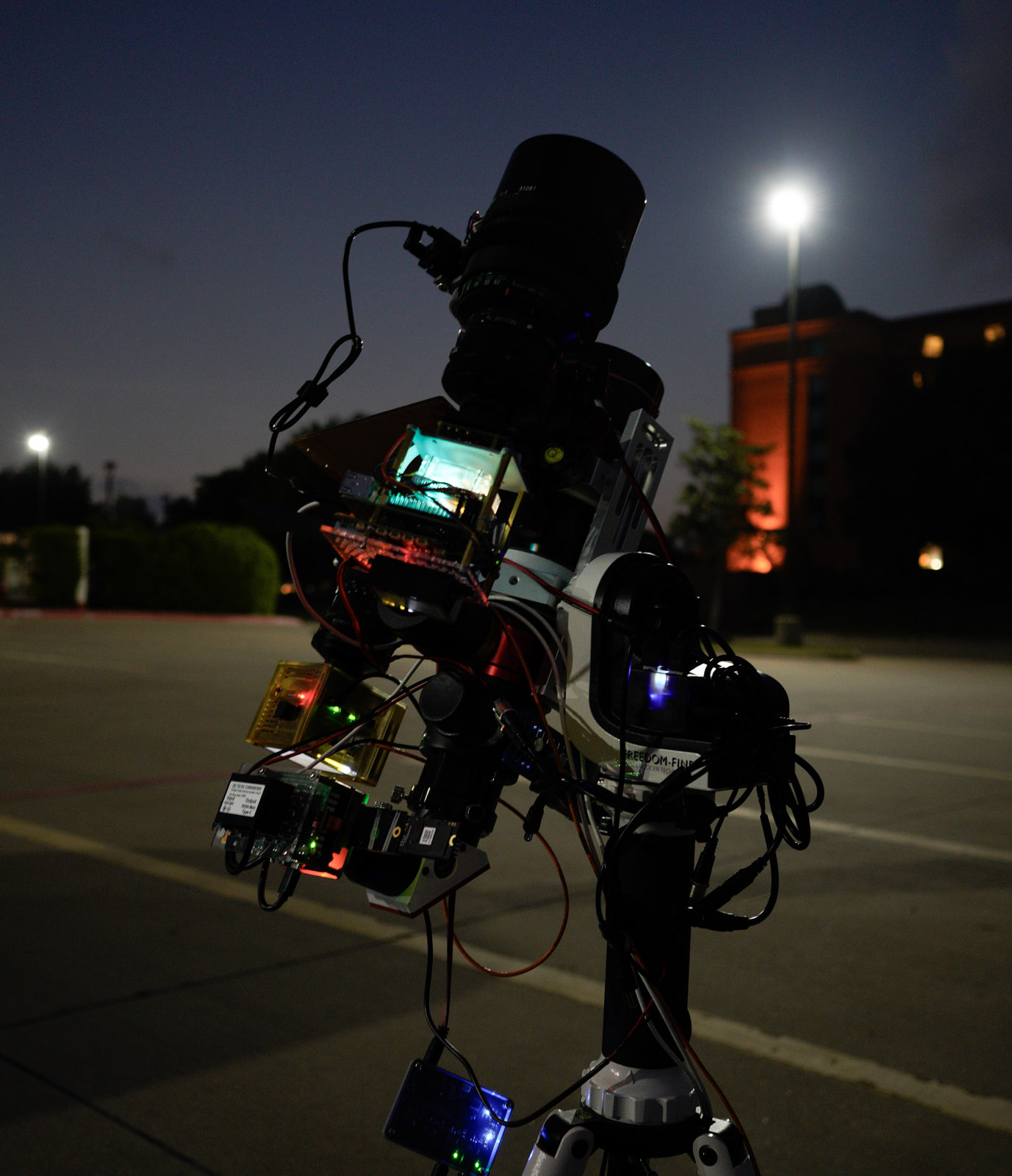
Telescope and Lens Setup with Enhanced Alignment
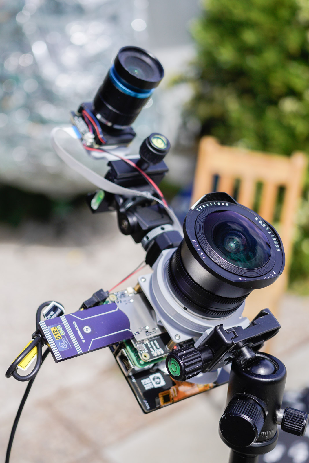
The main telescope I’m using is still the LS60MT from LUNT, but this time I’ve also mounted a 500mm FD lens on top using two fine-tune mounts for precise alignment. Additionally, a third wide-angle lens is mounted on the side using a finder scope mount.
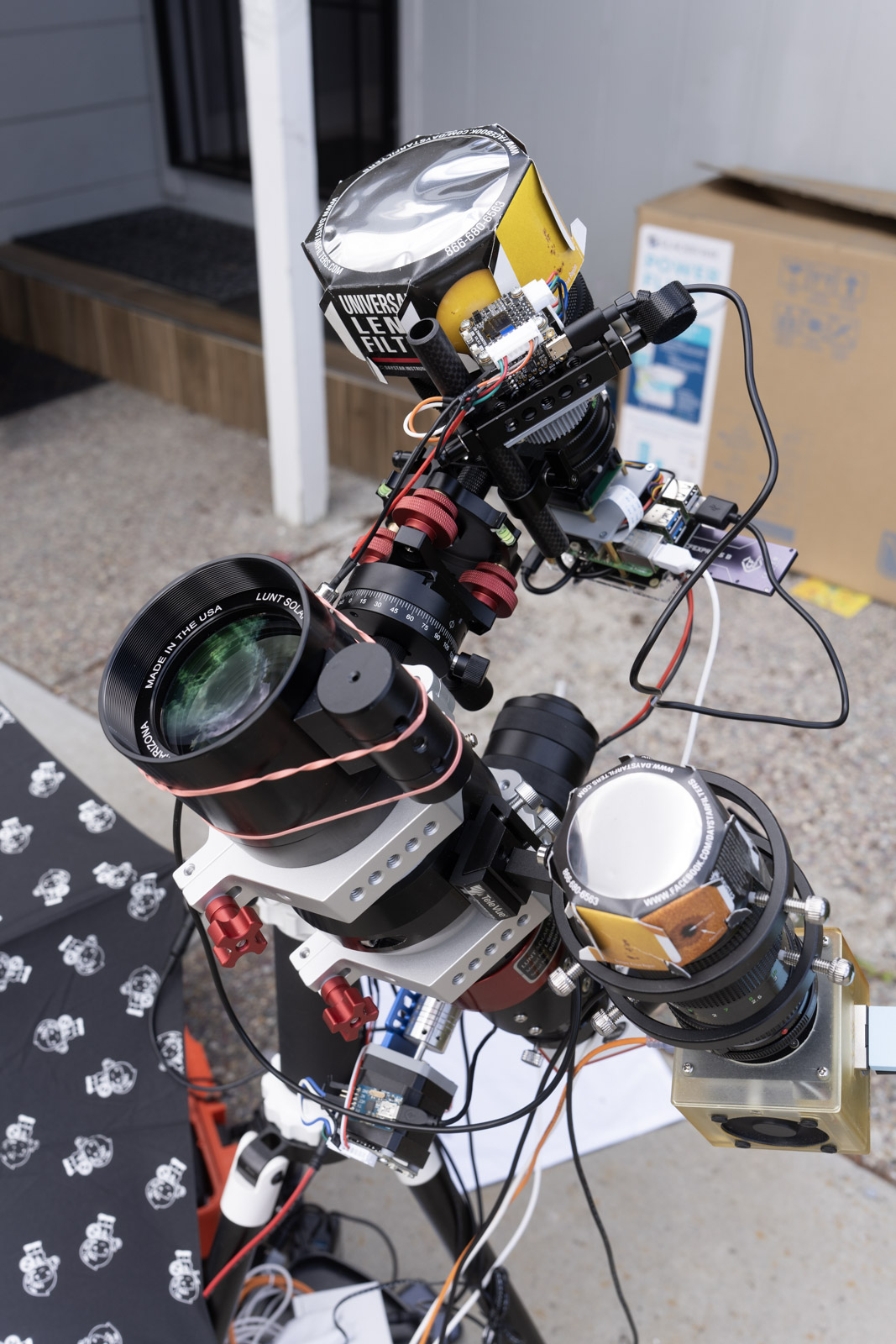
The 500mm FD mount lens requires a focus tuner because manually achieving sharp focus is quite challenging (Totally not spoil the story).
Both focus motors are equipped with “smart” stepper motors that include a controller board to receive commands and report the current angle via UART. I connect these to the RPI5 using a USB to serial converter. Current angle report is crucial for determining if the motors are actually turning, as the steps are too small to overcome the resistance on their own sometimes.
Camera Package Result
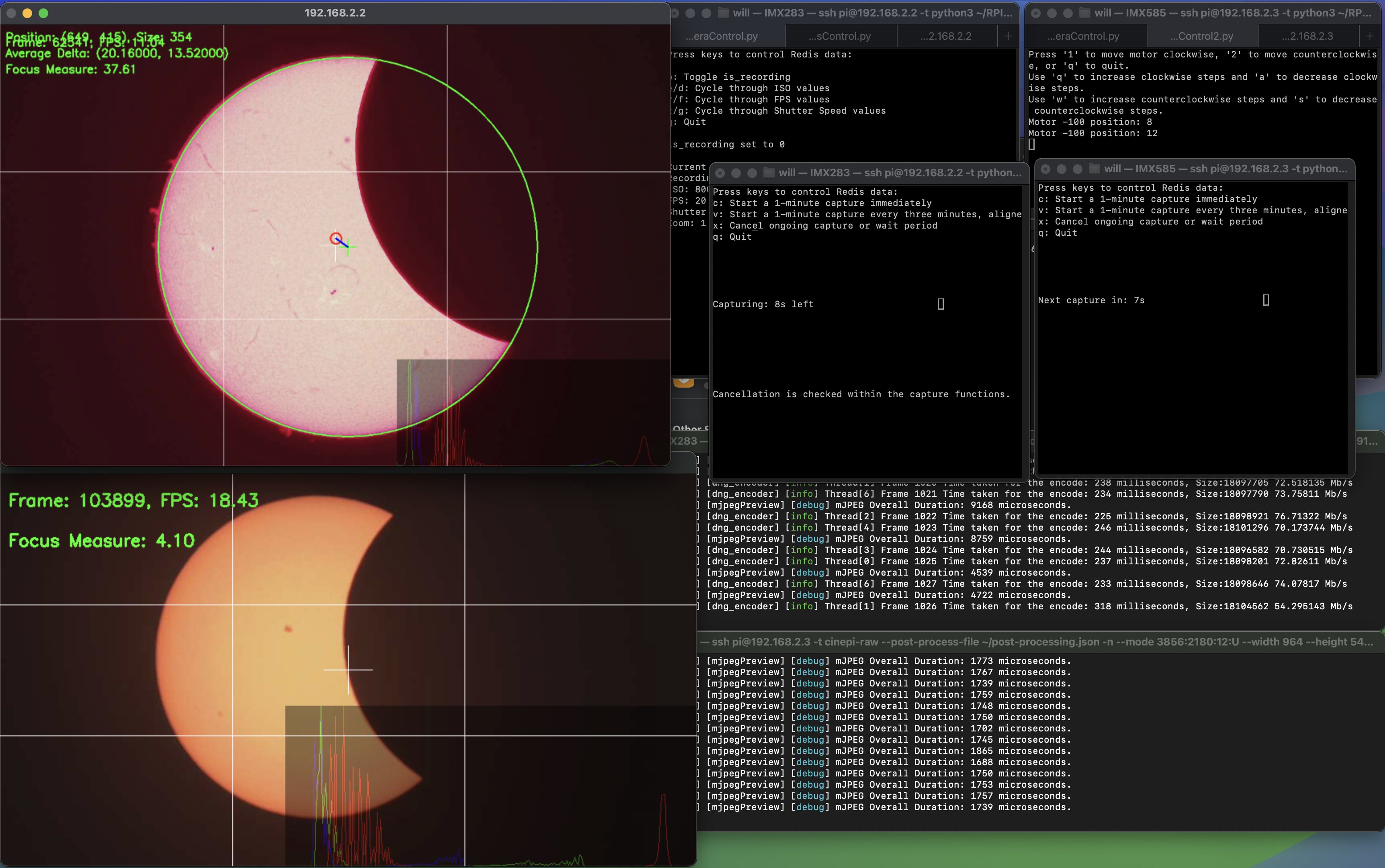
Here are the results from the two cameras set up with my enhanced telescope system:
-
OneInchEye Camera for the Main Telescope:
-
StarlightEye Camera for the Secondary Lens:
Regarding the power setup, I used a converter which you can find here. This converter is quite versatile, accepting 8V to 32V input and converting it to 5V with 5A output, complete with proper USB-PD support. This ensures that RPI5 receive stable and sufficient power. (More on that later).
Lastly, the power setup is managed by the PowerMux Hub, designed to ensure stable power to the entire systems.
PowerMux Hub: Ensuring Sustained Power Supply
The PowerMux Hub is my solution to the significant power demands of running multiple devices—specifically, two Raspberry Pi 5 units and one Compute Module 4—during extended operations such as observing a solar eclipse. This event lasts approximately three hours from the initial contact of the moon with the sun. Given these extended durations and the limitations on battery pack sizes for airline travel, I couldn’t rely on larger portable power stations like the Jackery portable power stations.
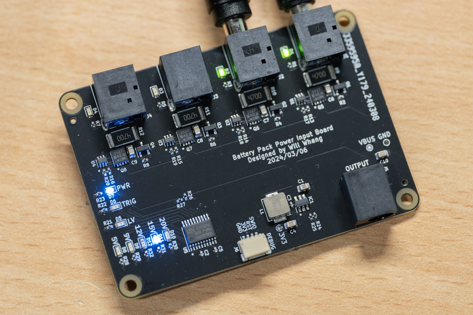
To address the challenge of needing multiple power sources and the capability to hot-swap them as necessary—a feature that’s also useful for various other projects—I turned to KiCad to design this hub. I utilized the ideal diode circuit from previous projects, replicating it several times within the design. Additionally, I incorporated a CH32V003 microcontroller for voltage monitoring and to trigger dummy loads. These dummy loads are for keeping the battery banks active and preventing them from shutting down during periods of no power draw.
What makes the PowerMux Hub particularly special for me is that it was the first board I designed without creating a physical prototype first. I sent the design directly to be manufactured and assembled (PCBA), and to my relief, everything worked perfectly on the first try. This hub now plays a critical role in ensuring that all my devices have a reliable and continuous power supply, enabling uninterrupted observations and recordings.
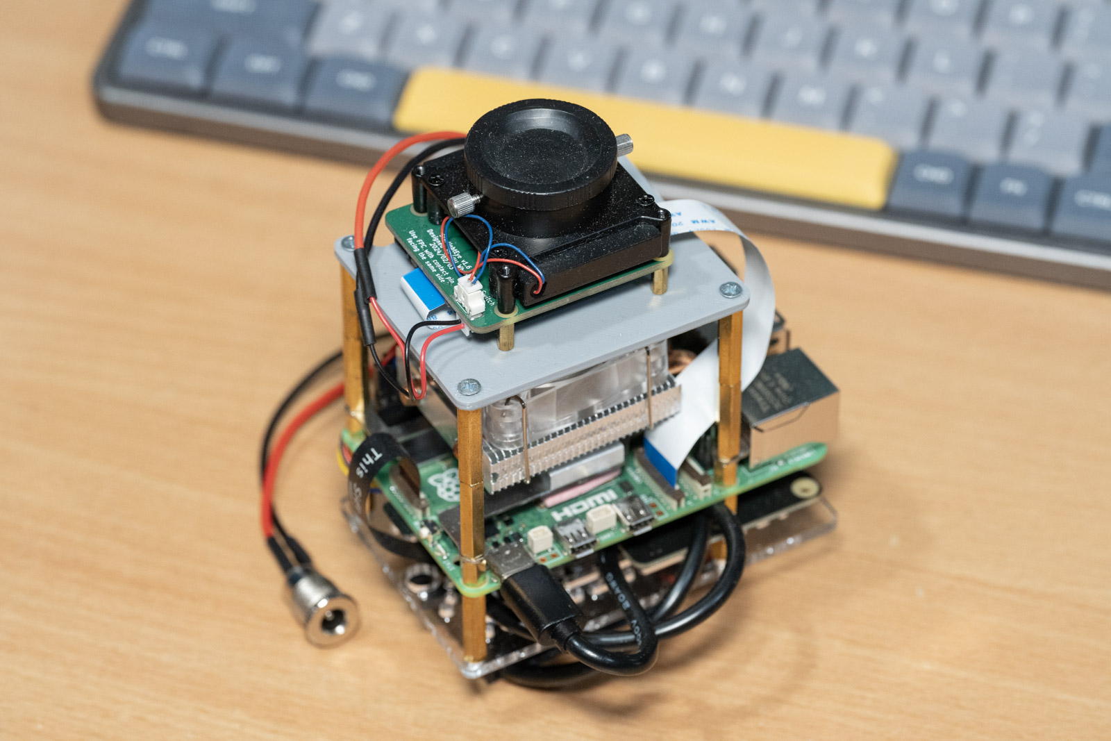
Passive E-mount Timelapse Camera
Since I’m going to bring backup for the important parts like RPI5/OneInchEye/StarlightEye, I used the backup parts to built a camera capable of ultra-wide angle timelapse photography. This setup is versatile enough to use both the OneInchEye and StarlightEye cameras simultaneously, allowing them to capture timelapses independently. It also includes a HyperPixel 4.0” square display, which is essential for setting up the view.
For the lens adapter, I constructed a passive E-mount adapter. This adapter lacks digital controls, which means I can’t use it with the digital lenses from my Sony camera. However, I specifically built this setup to use with TTArtisan 7.5mm fisheye lens, which effectively becomes a 31mm wide-angle lens on this camera due to the crop factor. This manual lens was chosen to specifically overcome the crop factor limitation by brute force.
Software - CinePi-Raw
Having discussed the hardware setup extensively, let’s now turn our attention to the software required to process the output from either the StarlightEye at 4K 60FPS or the OneInchEye at 20Mpix 21FPS. The core software here is CinePi, developed by Csaba Nagy, which is vital for capturing images during a solar eclipse.
Overall Capability
CinePi-RAW is capable of recording in CinemaDNG format, which means it can save RAW images as DNG files for each frame, complete with additional timecodes in the EXIF field. This capability allows me to maximize the performance for OneInchEye, recording at 20Mpix per frame (5472x3468) at 21FPS, and for StarlightEye, up to 4K 60 FPS. The advantage of RAW over traditional formats like H.264 or HEVC is the enhanced dynamic range and greater flexibility in color adjustment during post-production and also for me: astrophotography post process.
CinePi-RAW also produces a lower resolution mJPEG stream, which can be used to remotely monitor the live preview or to have a separate program for the preview that operates independently from CinePi-RAW. This setup essentially provides a remote RAW image capture system suitable for telescope use.
However, the main issue with raw capturing is the huge file sizes; previously, I was capturing 570Mb/s of data (5472x3468x12bitx21FPS) onto a CFexpress card. This time, Csaba Nagy has managed to introduce compression that reduces the file size from 40MB (RAW 16 bit if captured using rpicam-raw) to just 18.2MB. The reduction depends on the scene complexity, but generally, I’m seeing a reduction of 50% or more in file sizes.
Performance and RPI5 Limitations
The input for the RAW output pipeline offers only two options: 16 bit uncompressed and PiSP compressed 8 bit. The architecture is designed so that PiSP-CFE outputs a consistent image format regardless of the sensor’s bit depth. However, because sending 16 bit data consumes significant bandwidth, there is an 8 bit compressed PiSP format that uses a logarithmic scale to reduce bit depth.
CinePi-RAW requests the 16 bit uncompressed format from the driver. One might think that shifting the bits would be quick enough with the Cortex-A76 cores, but it actually requires a boost from Neon instructions to shift and pack the data. If you’re wondering, storing the 16 bit RAW directly without shifting the data increases file size by 25% (from 12bit raw).
The performance of libtiff is another concern. Even though I use libtiff to write “files” in memory buffer and then flush them to disk, the last step for libtiff writing the actual image is essentially a memory copy process, which I aim to eliminate (more on this later). The EXIF fields are relatively fixed in structure, allowing me to manually build the EXIF IFDs in C and have the shifting function output directly to the memory buffer.
Another surprising discovery relates to memory bandwidth. Memcpy is a common bottleneck in systems, often using more resources than necessary and dragging down performance. However, what I didn’t expect was that the memory bandwidth accessible by the CPU group as a whole isn’t great on the RPI5.
I ran a quick memcpy test based on a program called mbw on both RPI5 and RPI4 to see the available memory bandwidth, and here are the results:
| Raspberry Pi 5 | Thread BW | Total BW |
|---|---|---|
| 1 Thread | 5053.9 MiB/s | 5053.9 MiB/s |
| 2 Thread | 2048.4 MiB/s | 4096.8 MiB/s |
| 3 Thread | 1129.7 MiB/s | 3389.2 MiB/s |
| 4 Thread | 705.7 MiB/s | 2822.7 MiB/s |
| Raspberry Pi 4 | Thread BW | Total BW |
|---|---|---|
| 1 Thread | 2093.5 MiB/s | 2093.5 MiB/s |
| 2 Thread | 1060.1 MiB/s | 2120.2 MiB/s |
| 3 Thread | 553.1 MiB/s | 1659.5 MiB/s |
| 4 Thread | 421.1 MiB/s | 1684.6 MiB/s |
Although the RPI5 shows better performance than the RPI4, the total bandwidth drops significantly with more threads engaged, indicating that the compression process needs to consider bandwidth limitations. The compression used is lj92, with Neon-accelerated routine, but at this point my brain has stop working because of arm intrinsics (I have enough from writing the bit packing/shifting function) and you will have to check Csaba Nagy’s awesome work on the Neon optimized lj92 compression.
While writing this blog post, I came across the raspberrypi_axi_monitor, with dtparam=axiperf=on you can see the AXI perf numbers in real-time, here is a screenrecording while I run the StarlightEye with CinePi and recording/stop recording:
However I’m still not fimilar about how to interpret the results, given that there is no system block diagram for the BCM2712 right now.
Lastly, despite the capabilities of the RPI5, it lacks a hardware encoder. While cinepi-raw have an mJPEG stream output, the absence of a hardware encoder limits potential performance enhancements as it needs to be software compression.
In the end, while I talked about dual camera support in the solar eclipse post back in 2023, the performance and memory bandwidth limitations of the RPI5 make me think it is unrealistic to sustain dual 4K 30p video recording. Dual camera operations for still images are feasible, but continuous 4K 30p video recording might not.
One more limitation though not related to the process is the PMIC, this is also quite annoying for my other RPI5 projects that PMIC has a strict 4.8v low voltage cutoff. Instead of warning the users about low voltage, PMIC will shutdown the systems without any kind of automatic restart, which is very annoying for some of my RPI5 remote setup usage like a ACARS receiver. This is also the reason why I need a DC-DC converter for each RPI5, otherwise just the long USBC cable voltage drop will randomly shuts the camera off.
Telescope Monitoring Software for Solar Eclipse
The monitoring software for the telescope remains unchanged from the previous solar eclipse. It utilizes openCV to determine the position of the sun and calculates any positional offsets. These calculations are then relayed to another daemon responsible for adjusting the telescope’s alignment. This daemon sends commands to correct the telescope’s orientation by compensating for any detected skew.
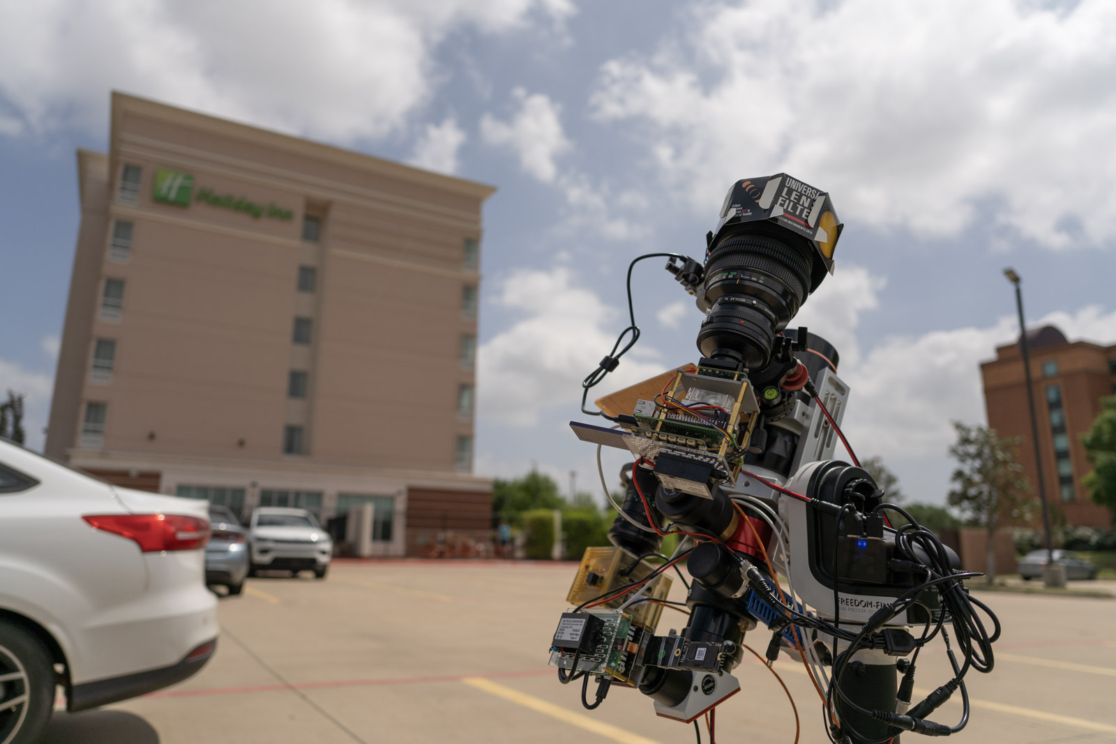
Field Test and Planning for Solar Eclipse Observation
With all the equipment set up, the next step involved conducting field tests to ensure everything functioned as intended:
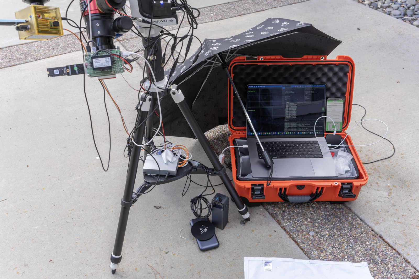
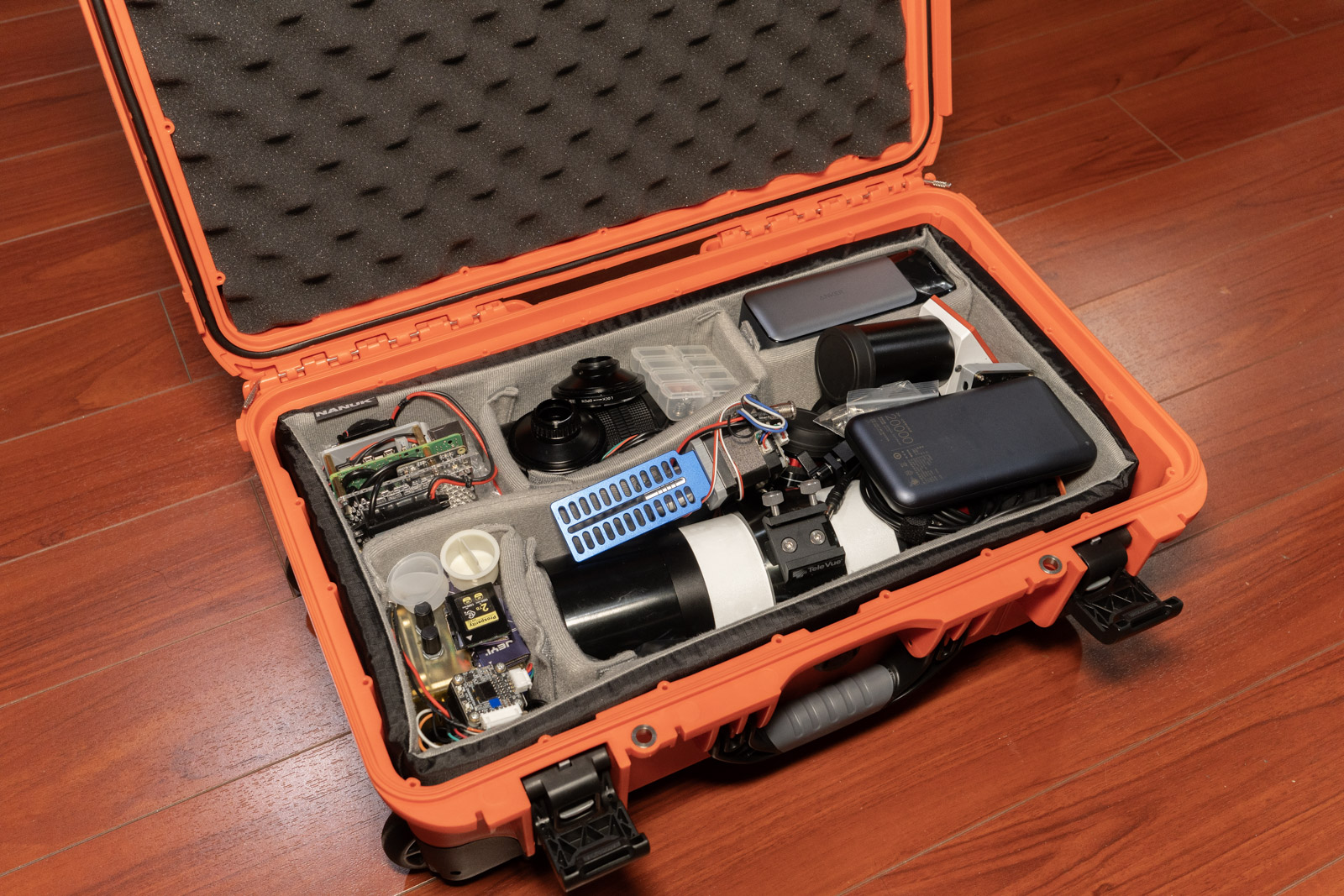
Additionally, I performed packing tests to confirm that all the necessary gear could fit into a carry-on case:
Challenges Encountered
Power Consumption: One significant issue encountered during the tests related to power consumption. Running all three Raspberry Pi 5 units along with the Compute Module 4, especially with the SoC overclocked and writing to an NVMe SSD at ~400MB/s, proved to be quite power-hungry, consuming about 40W in total. Most battery banks struggle with such a high draw, especially at 12V, which would require more than 3A of current whereas many battery banks typically provide only 1.5A or 2A at this voltage. To overcome this, I opted to use a higher 15V PD setting so that my battery banks could adequately support the entire system espically during hotswap.
Storage Capacity: Another challenge was storage. Even with data compression, capturing the entire 3-hour duration of the solar eclipse event was not feasible because each frame is approximately 18.2MB. Therefore, the strategy was to selectively capture footage: 1 minute of every 3 minutes for a timelapse on the main telescope, and 10 seconds every minute for the secondary lens. During the totality phase all cameras would record at full speed to capture this critical period in detail for ~10 minutes.
Actual Run of the Solar Eclipse Observation
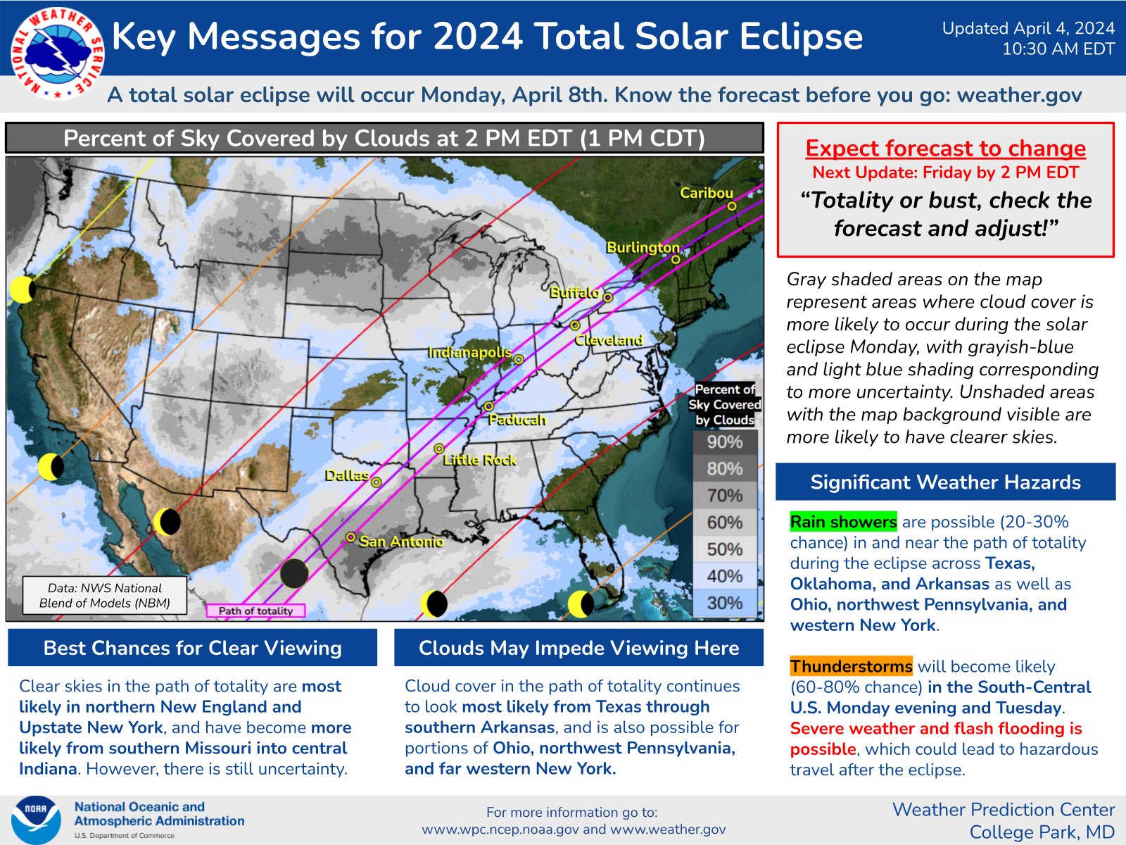
With everything prepared and tested, the actual day of observation was filled with both anticipation and concern over weather conditions.
Preparation and Travel Plans
The plan was straightforward a couple months ago: travel to DFW, stay in a hotel nearby, and then fly back home after the event. As the day approached, I closely monitored the weather forecasts, which, to the dismay of many, predicted potentially severe weather conditions. But it is too late to change the plan for me, because my parents are also traveling with me this time. The NOAA even issued a thunderstorm warning for the morning of the eclipse.
On the morning of the event at 9 AM, the sky was ominously covered with clouds.
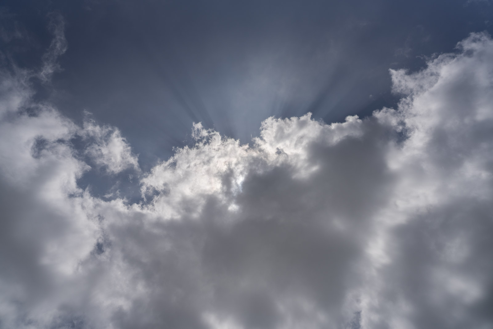
This is me in the morning when I walk out of hotel room.

Surprisingly and thankfully, the weather cleared up enough to allow for some observations. While clouds intermittently covered the sun, I was able to collect more data during this eclipse than last year’s eclipse.
Here is the timelapse Video from Wide angle Timelapse camera backup system during the eclipse.
Encountered Issues
Despite the success in data collection, there were a few setbacks:
Camera Sensor Swap Issue: In a last-minute decision, I opted to switch the OneInchEye for the StarlightEye in the CM4 camera to potentially improve the footage. Although I tested the camera to ensure it functioned, I didn’t perform a stress test. Unfortunately, this oversight led to memory capacity issue under the sustained framerate demands (i.e I set the framerate too high, that the disk write can not sustain), causing the system to terminate the recording process and miss some critical shots.
Focus Issues on the Secondary Camera: The secondary camera was slightly out of focus. In hindsight, I should have adjusted the focus based on the landscape rather than trying to set it by directly viewing the sun.
StarlighteEye + secondary lens During Totality
With the normal color images done, the next step is to process the remaining H-Alpha images from the main telescope.
Post-Processing the H-alpha Solar Eclipse Data
Once everything was packed up and I returned home, it was time to dive into the post-processing phase. This process was similar to the one I used previously, but with some modifications to streamline the HDR processing.
HDR Processing Simplification
Previously, I utilized openCV’s HDR functions, but this time I opted for a simpler method. I adjusted the green channel using a multiplier based on the statistics gathered from the ratio between the red and green pixel readings, then capped the results at 14-bit depth.
Initial Observation in Lightroom
Upon opening one of the DNG files directly in Lightroom, you can observe that the red channel appears saturated from the fact that H-alpha filter predominantly captures the red channel (656 nm), but it was showing closer to white in the center due to saturation.
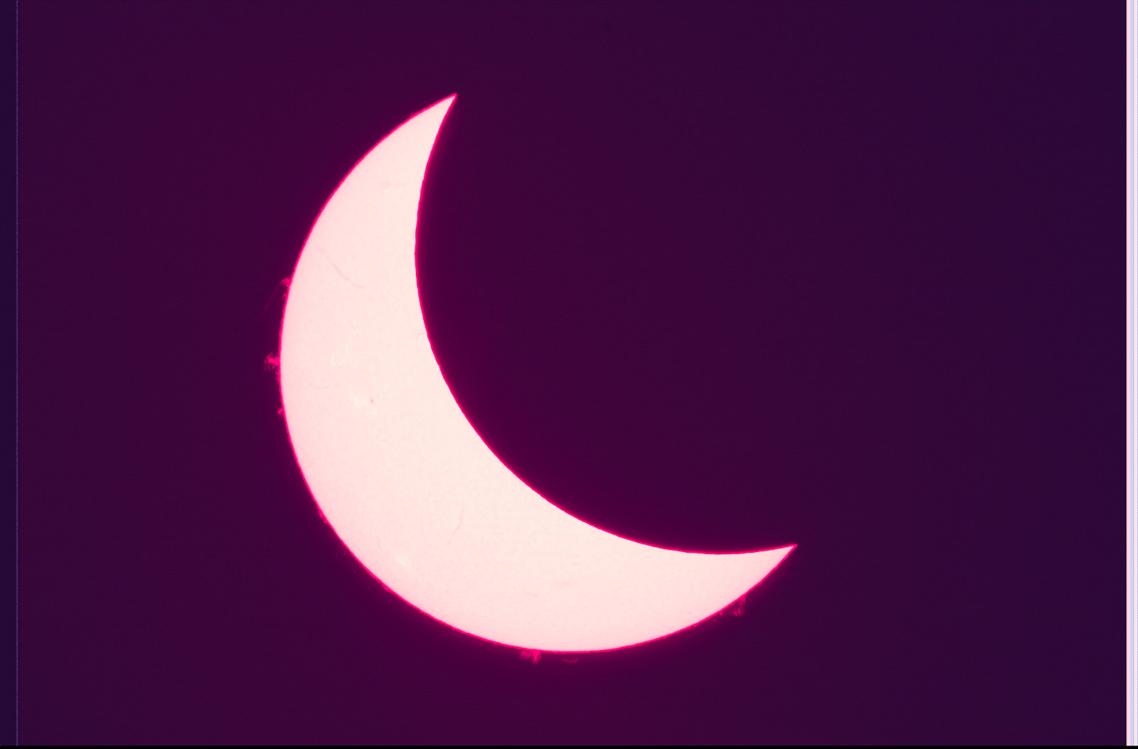
This is intentional because I want to have the green pixels get the main data instead.
Channel Separation and Merging
The next step involved separating the Bayer RAW image into its constituent Red, Green, and Blue channels, which are handled separately:
I then merge the Green and Red channels to achieve the final results:
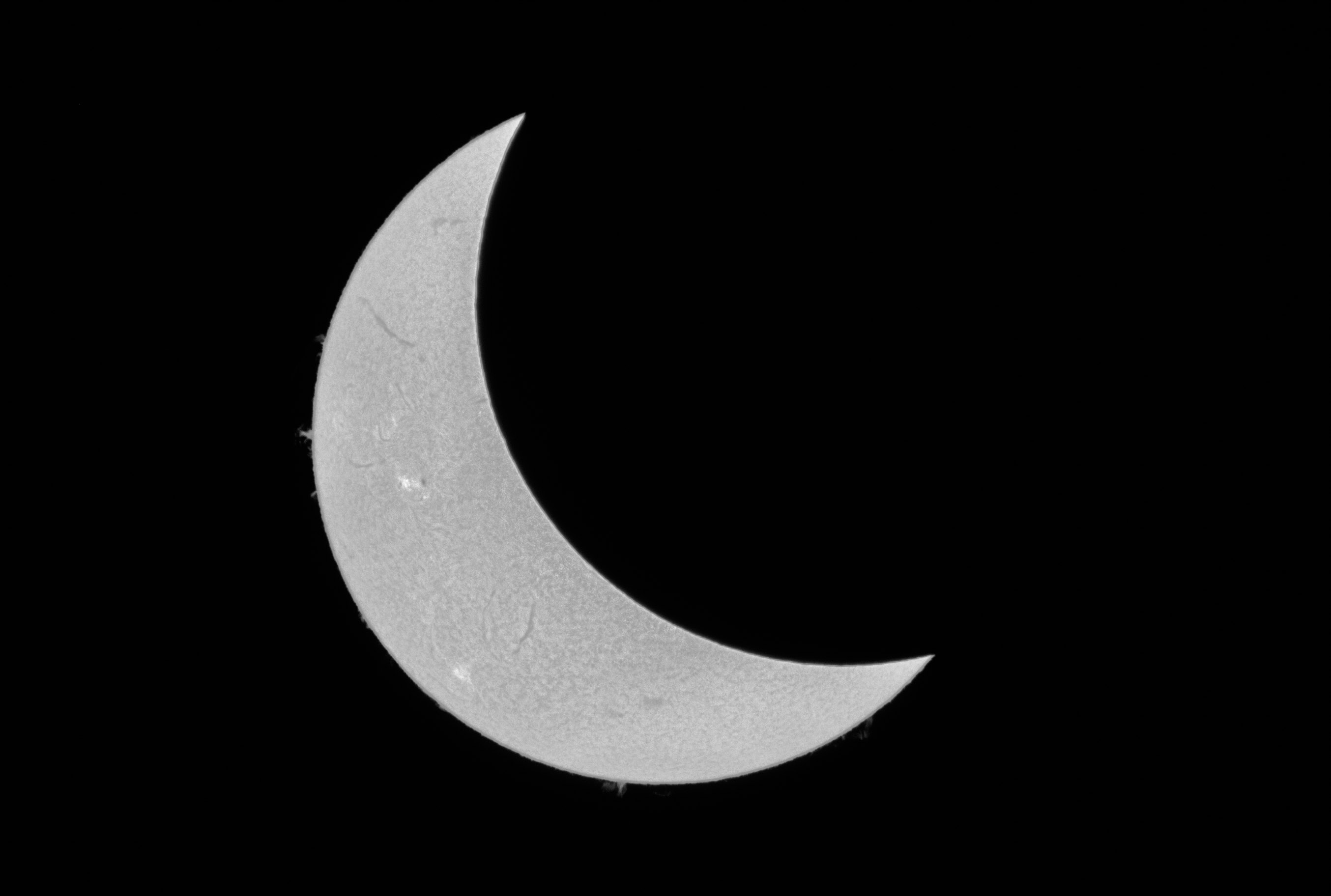
Image Stacking and Enhancement
With the frames processed into monochrome HDR images, I moved on to stacking the images using Autostakkert that evaluates multiple factors like image quality and alignment, and then merges the best captures into a final image (i.e lucky imaging):
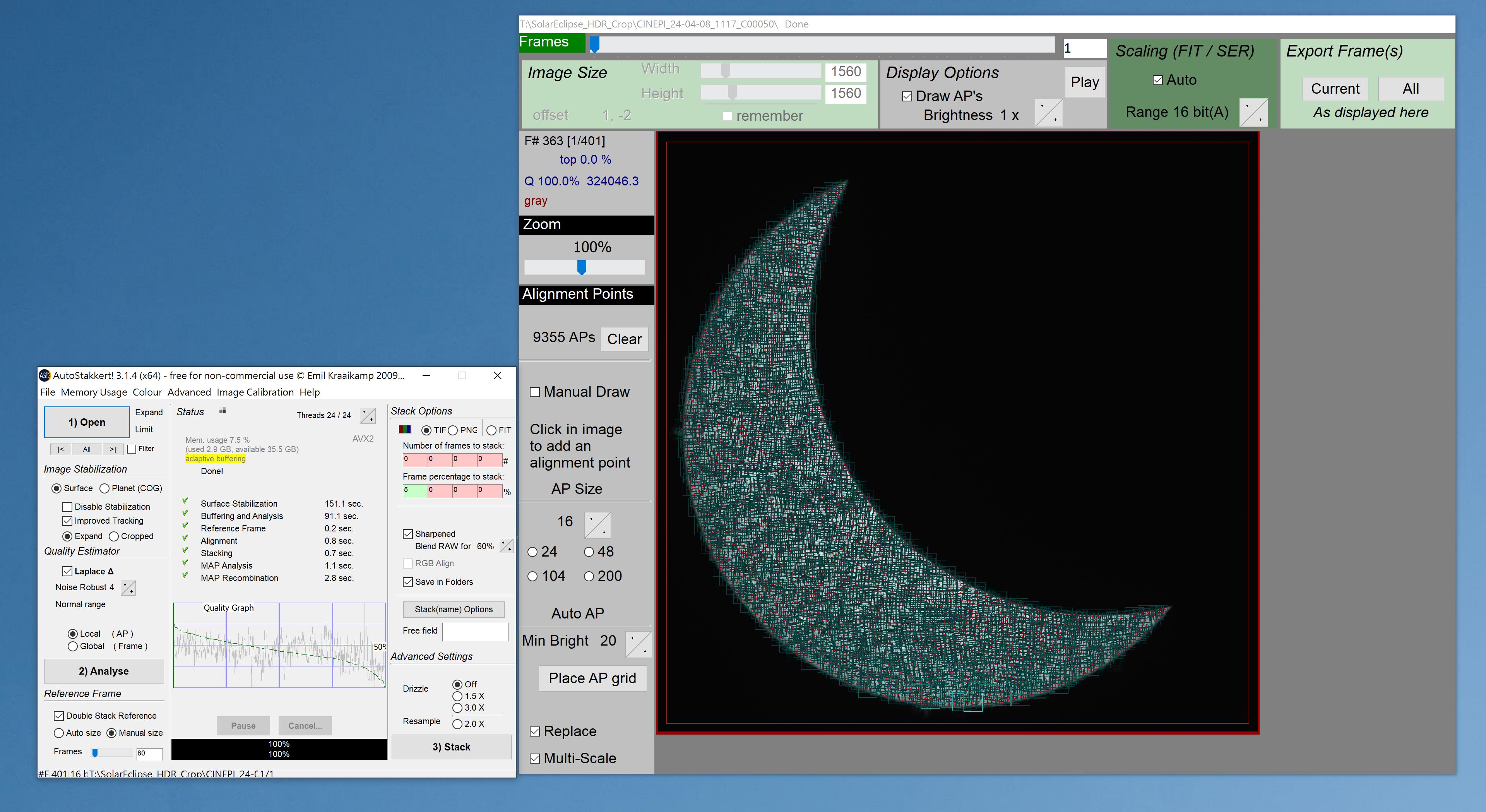
Here’s the output from the stacking process:
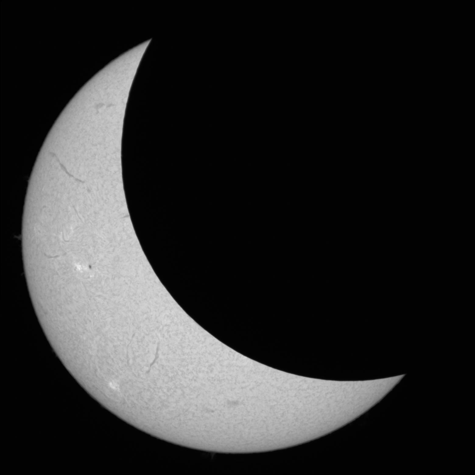
To enhance detail, Autostakkert can also apply sharpening adjustments:

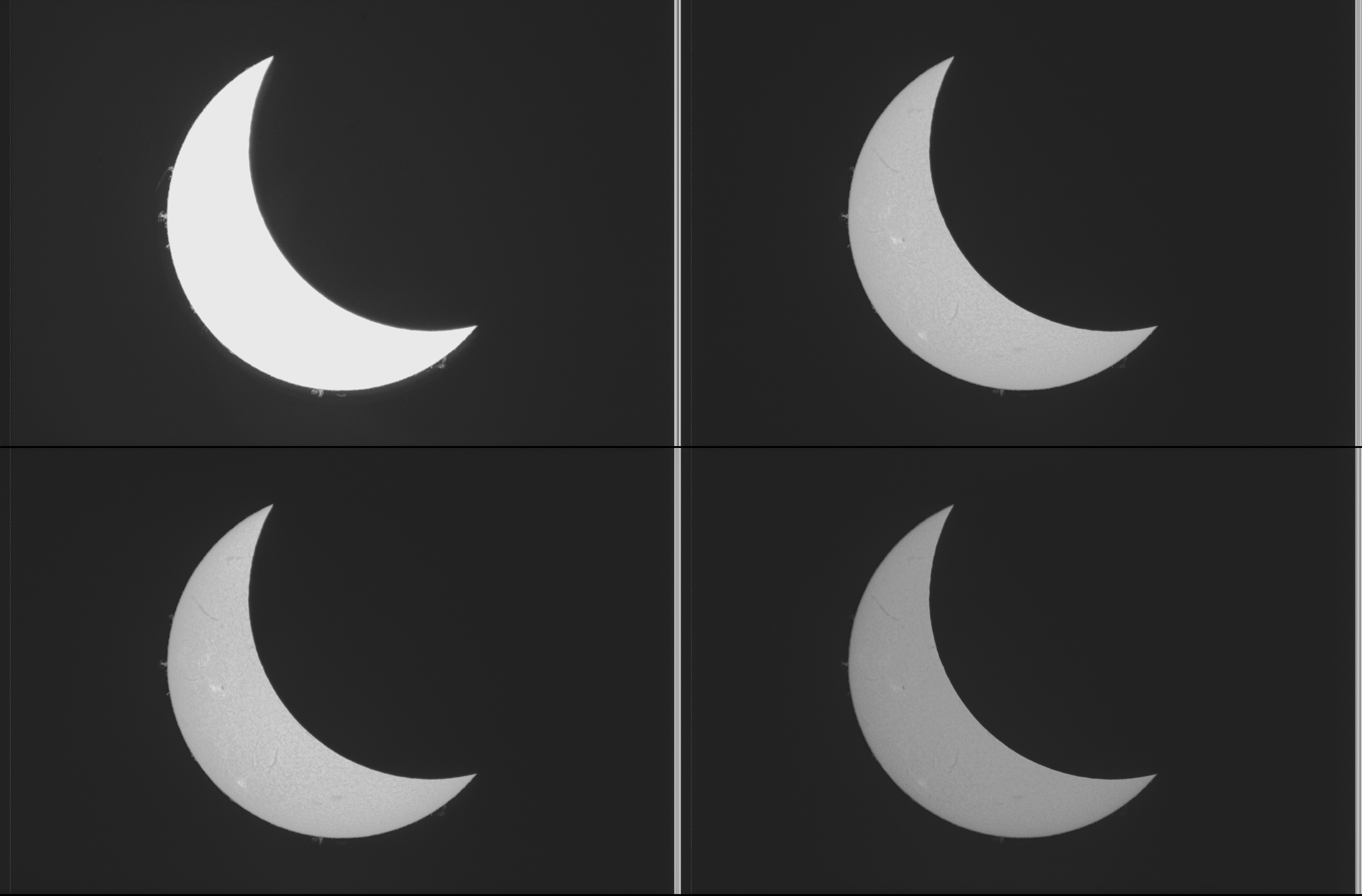
Finally, after processing all data, we have the image series of the eclipse:
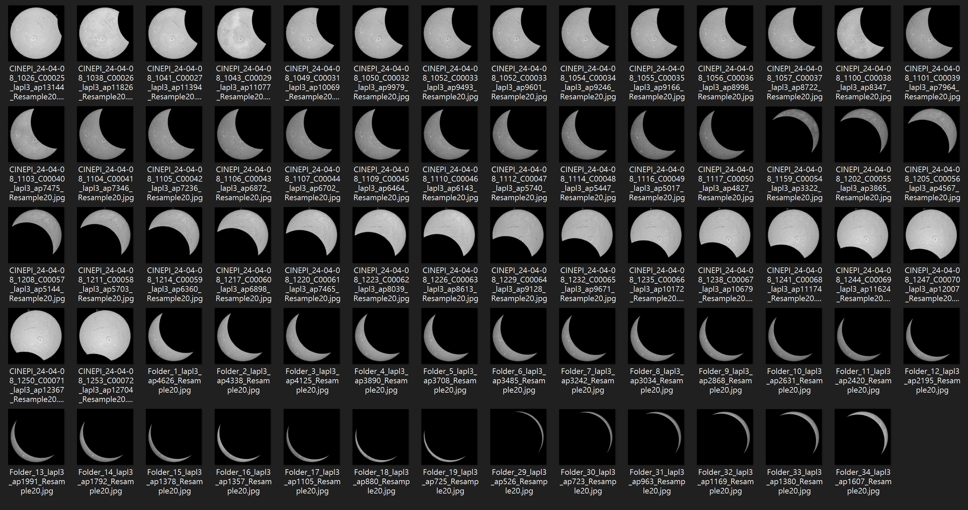
Result
The results from the solar eclipse observation were truly spectacular. Here’s a GIF that shows a timelapse of the solar eclipse, demonstrating the dynamic changes during the event:
Also here is a short clip showing some of the recording.
The totality phase was an awe-inspiring experience. Witnessing a 360-degree sunset and the sudden darkness was remarkable. The drop in temperature, the illumination of streetlights, and their subsequent fading contributed to a surreal atmosphere.
Here’s an image captured during the totality, showcasing the darkened sky and the surrounding environment:
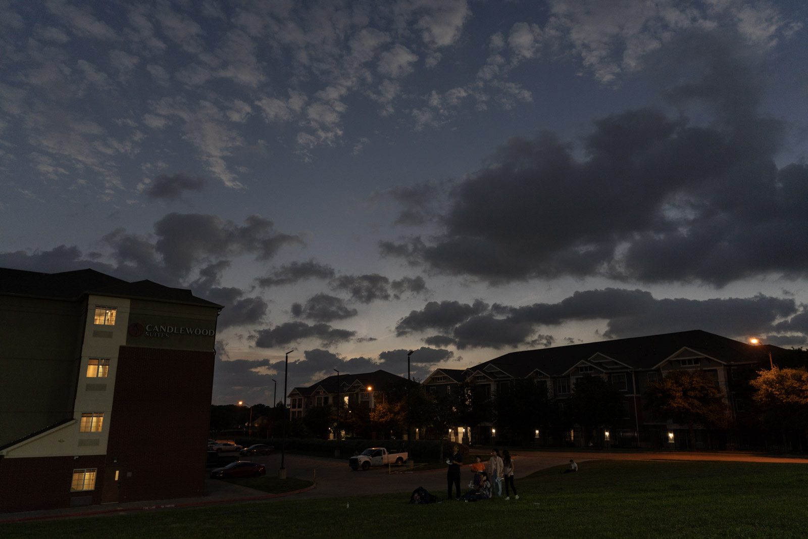
Now you see that the secondary camera actually has a RGB fan in it.
Future Plans
Exploring Alternative Single Board Computers
While the Raspberry Pi has served well for my projects, the platform’s limitations have led me to consider other options. Many makers have turned to Rockchip-based SBCs due to their impressive specs and performance. However, my experience with these boards has been less than ideal for camera applications due to poor documentation and limited support for connecting diverse camera modules. This has been frustrating, as these boards often boast great specs and include CSI-2 connectors but lack practical guidance for using them effectively.
Promising Alternatives
-
BeagleY-AI
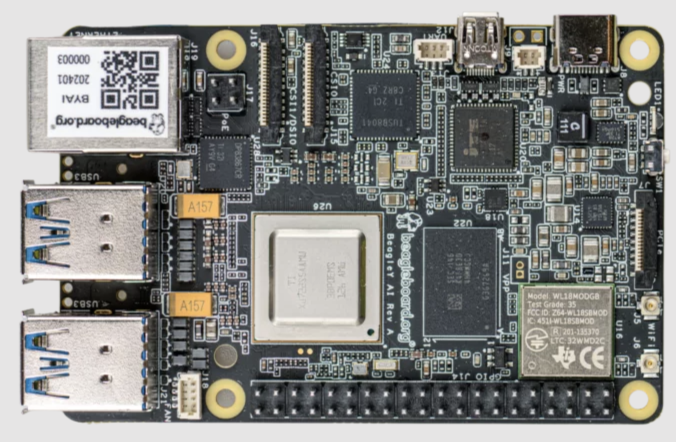
The BeagleY-AI, based on Texas Instruments’ new AM67A chip, seems promising. This board offers a 600MP/s ISP, supports 16-bit input RAW format, and features line support up to 4096. It also includes a video encoder for both H.264 and HEVC, along with PCIe 3.0 x1 lane and a 16-pin FPC connector. These features make it an excellent candidate for the StarlightEye camera, which requires a high data throughput for 4K 60p recording. TI has also provided extensive documentation on camera integration and usage like AM6xA ISP Tuning Guide or Multimedia Applications on AM62A and finally AM62Ax Linux Academy on Enabling CIS-2 Sensor, which is a significant advantage.
-
Kakip
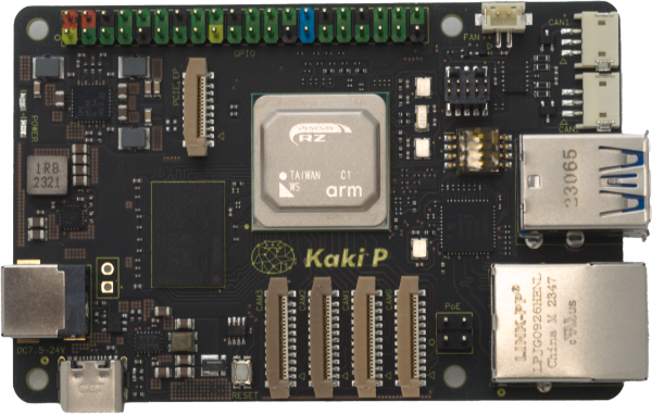
The Kakip board, based on the Renesas RZ/V2H, also looks intriguing. It features four MIPI CSI-2 22-pin 4-lane connectors and a PCIe 3.0 x1 16-pin FPC. This setup suggests potential for handling multiple high-throughput camera feeds simultaneously. Although the documentation on camera support is somewhat lacking and locked ai-sdk, otherwise their dynamically reconfigurable processor could be beneficial for image processing tasks.
-
Kria K24 SOM
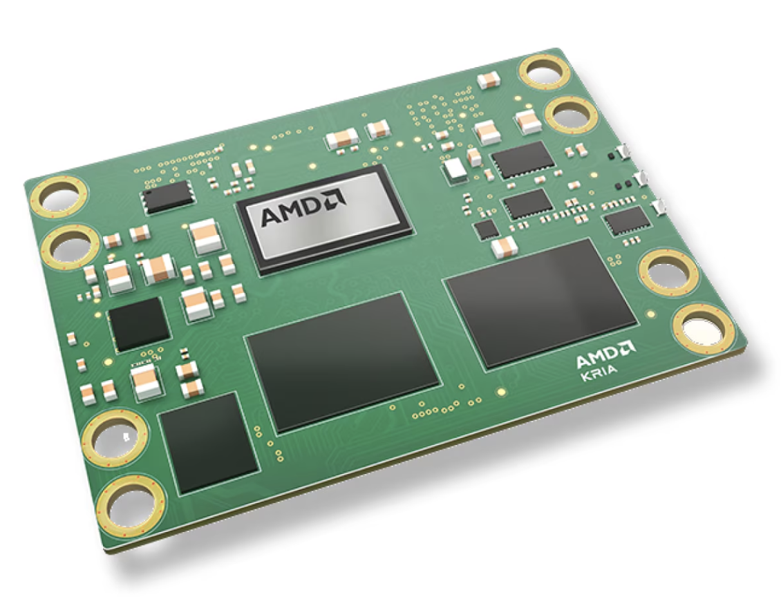
Another option I’m considering is the Kria K24 SOM by Xilinx. While it doesn’t have native MIPI CSI-2 hard IP support, it can be adapted for use with camera sensors using a logic level shifter, as suggested in their application notes. The support for PCIe 2.0 x4 lanes and USB 3.0 makes it suitable for interfacing with new sensors that do not use the MIPI standard.
And that brings me to the sensors that I have been cooking but lack the platform to drive it:
Future Sensor Development and Integration
As my project evolves, I am continually evaluating the capabilities and fit of various sensors to optimize for both solar and night-time astrophotography.
Current Sensor Configuration
The OneInchEye sensor has proven nearly ideal for my current setup, particularly with the LS60MT telescope, which has a relatively small aperture (60mm). This configuration closely matches the 2.4um pixel size of the sensor, making it well-suited for capturing full disk images of the sun with a 2x Barlow Lens. The 1” sensor size is sufficient for these applications, with larger sensors potentially being more beneficial for night-time astrophotography.
Exploring Larger Sensors
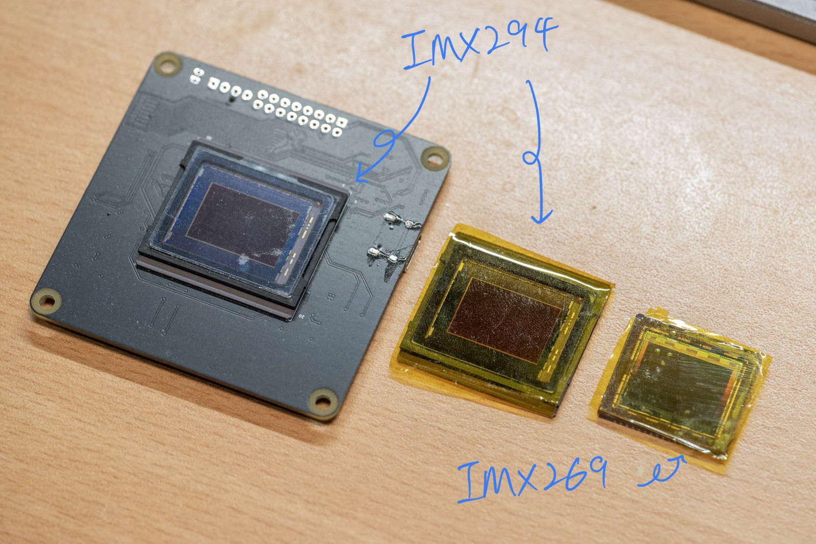
I am particularly interested in the IMX269, a 4/3rds sensor with a resolution similar to the IMX283, capable of outputting sub-LVDS at 27 FPS in full resolution. This sensor’s bandwidth and interface demands likely necessitate an FPGA-based solution, given its high data throughput requirements.
Another sensor I’ve explored is the IMX294, another 4/3rds sensor that utilizes MIPI CSI-2, which is more straightforward in terms of connectivity compared to sub-LVDS interfaces. However, this sensor has a slightly larger package than what my current C-mount setup can accommodate, and it offers a lower resolution of approximately 10Mpix. To adapt these sensors for use, I plan to develop a passive E-mount.
High Quality Camera Module Developments
It’s encouraging to see other manufacturers start going after the high-end sensor market for makers. Arducam recently released a new line of high-end cameras, some of which utilize the IMX283 sensor. These developments are promising as they indicate a growing interest and support for advanced imaging capabilities within the maker community. However, looking at the framerate spec it’s disappointing that these new models seems to be limited to 2-lane MIPI, which doesn’t fully leverage the capabilities on Raspberry Pi 5.
Arducam’s new camera announcement
And on the storage front….
PCIe 3.0 Hub Development
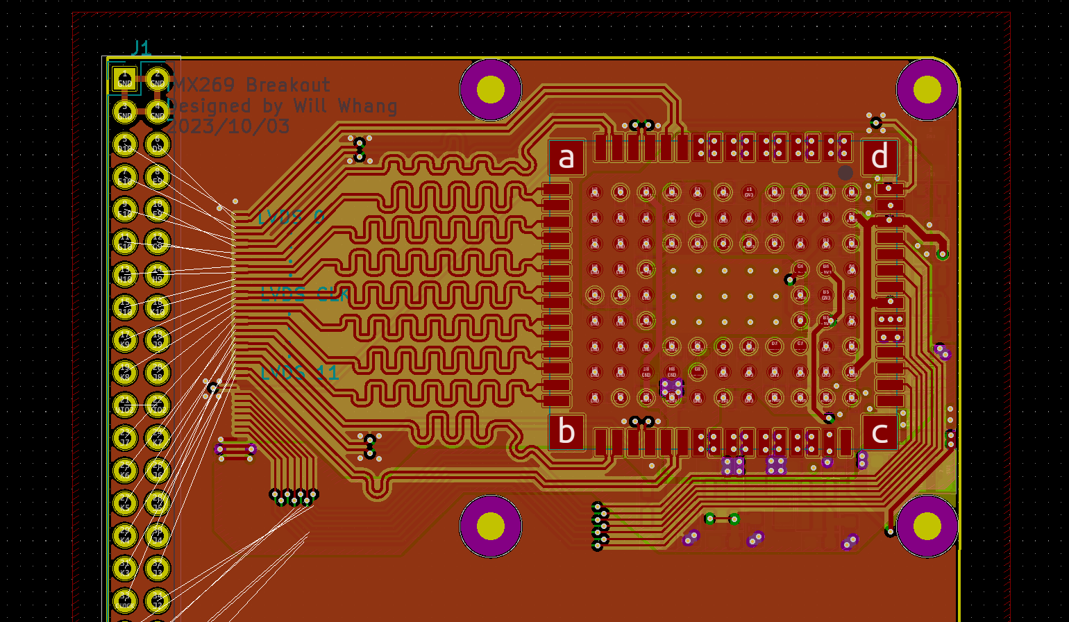
I’ve been interested in a particular PCIe hub IC for some time now, the ASM2806. Unfortunately, finding documentation for this PCIe 3.0 x2 lane to four PCIe 3.0 x1 lane hub proved challenging. Recently, however, I finally found a well-documented schematic that includes this hub, as well as a schematic for a 2.5GBE Intel chip.
Armed with this documentation, here is my unfinished PCB design for this PCIe Hub chip:
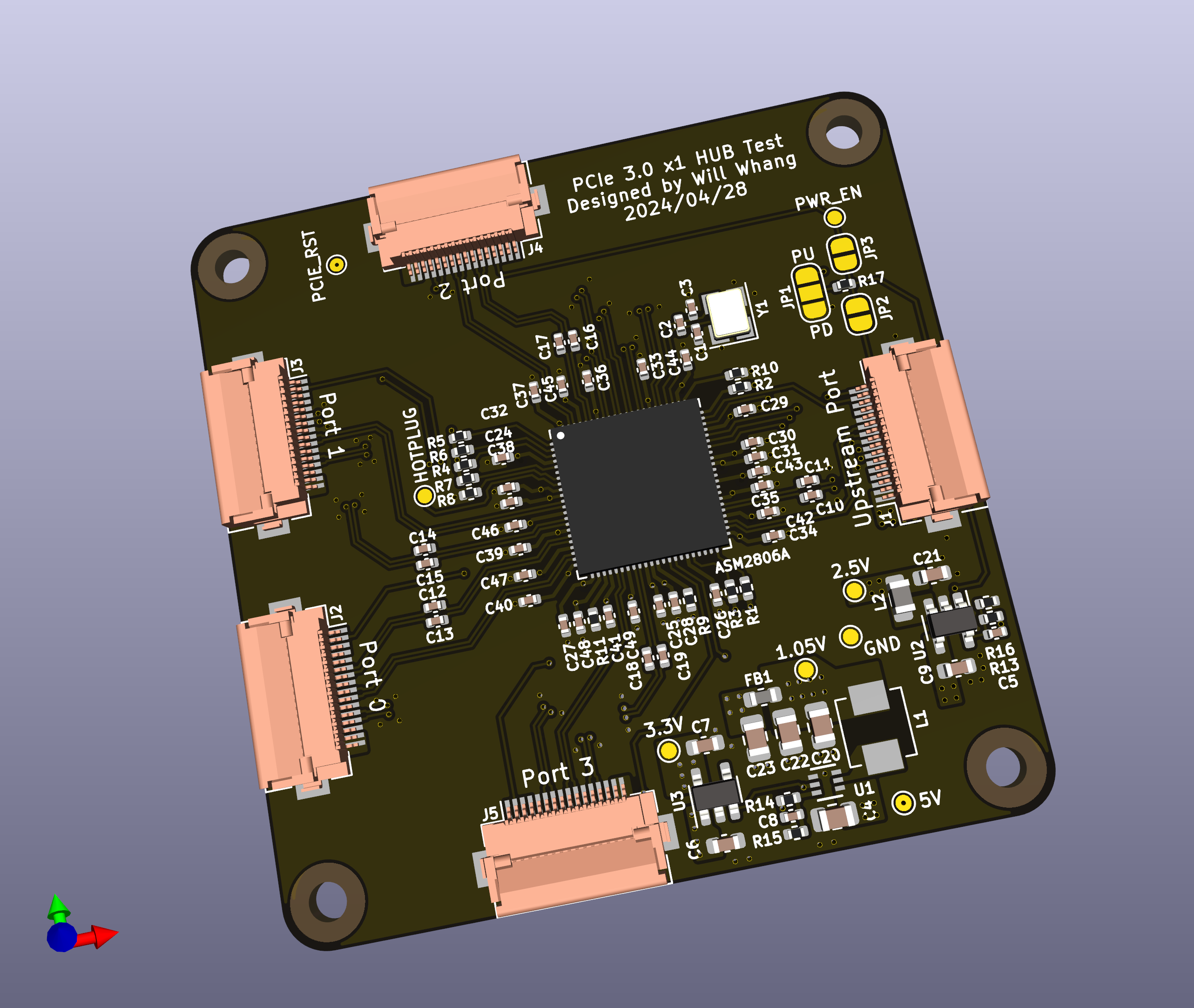
This development is currently for testing purposes. My plan is to incorporate this hub into the CFE Hat to allow for multiple card support, eliminating the limitation of being restricted to a single NVMe storage card. Although there are higher capacity cards (>2TB) available, 2TB NVMe cards are more common and frequently on sale, making this a practical and economical choice for enhancing storage capabilities.
Next Solar Eclipse
The saying “See your first eclipse, photograph your second” by Allison Johnson here resonates deeply with me, especially after my recent experience. I’m grateful that the system could capture the images with minimal input, allowing me to enjoy the totality with friends and family—a truly memorable experience without the need to constantly monitor the equipment. However, having gained this experience, I’m already thinking about improvements for the next eclipse.
One issue I noted was that the secondary lens was probably too zoomed in for the subject. Given that the corona can span two or more sun diameters, I might need to use a larger camera sensor (IMX294 or IMX269 if I get it operational) for that specific lens.
Another challenge is the HDR capability. I kept all the sensors in manual mode, but the dynamic range of the sensors couldn’t capture the totality without HDR. The IMX585’s ClearHDR and its 16-bit output have been tested on the RPI5, but there are issues with the RP1 expecting a different endianness than what the sensor outputs. You can swap the bytes in memory, but the statistics output from the PiSP-CFE will still be incorrect, causing failures in auto-exposure (AE) and auto white balance (AWB). (GitHub issue) ClearHDR stands out because it combines the HDR on sensor directly, that is just a workaround for those ISPs that can not/don’t want to handle HDR, but IMX294 is also capable of dual gain with a single exposure frame. (Fun fact, IMX294’s relatively low resolution is because this sensor is actually a quad-Bayer array that only outputs the combined Bayer pixels, so it’s actual resolution is at 4x of that, and this is how it can sample two gains with a single exposure, Sony use the four sub-pixels sample with different gain directly). RPI forks has been talking about HDR for some time now but I’m still quite confused on how it actually implmented, and what’s worries me is that presumably I want to combine the HDR myself with two High/Low gain streams in post, I’m not sure if RPI5 can even handles storing two streams fast enough.
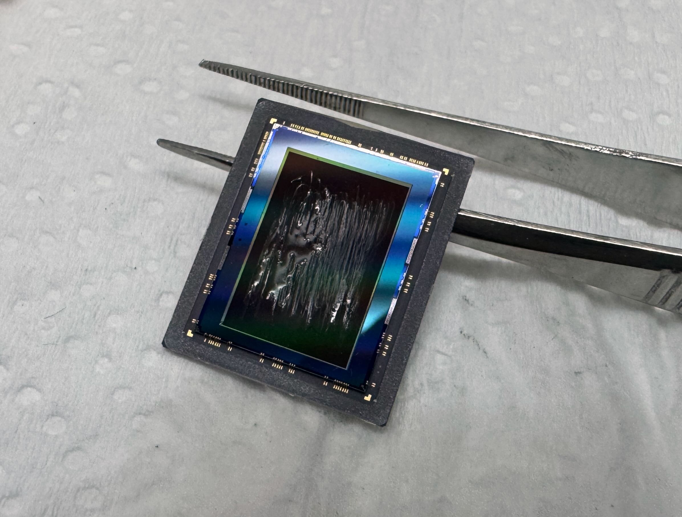
Lastly, the use of monochrome sensors is something I’m considering. The CFA-HDR method uses a trade-off by sacrificing resolution for HDR capability. There are monochrome sensors available, and one can even remove the CFA filters on sensors manually. I tried removing CFA filters on an IMX283 using a chemical method (DMSO) but was unsuccessful, and professional removal service on the other hand is costly.
I’ve also designed a CNC tool similar to a CPU delidding tool for this purpose:
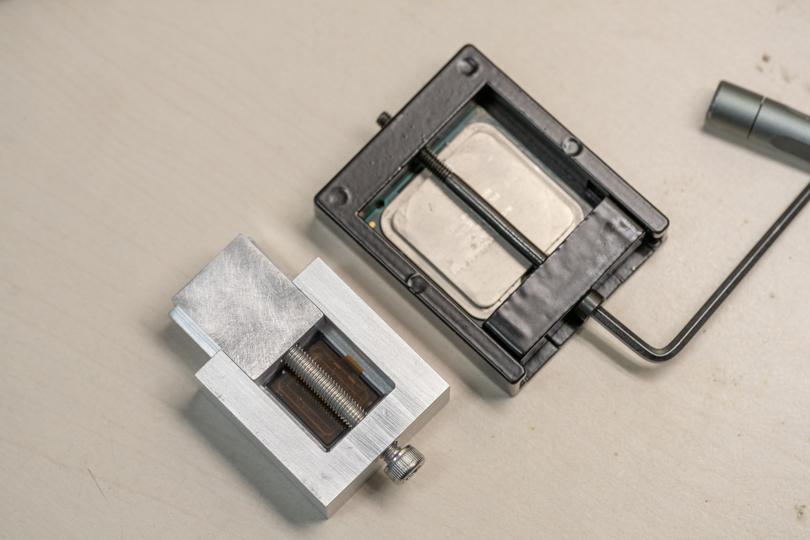
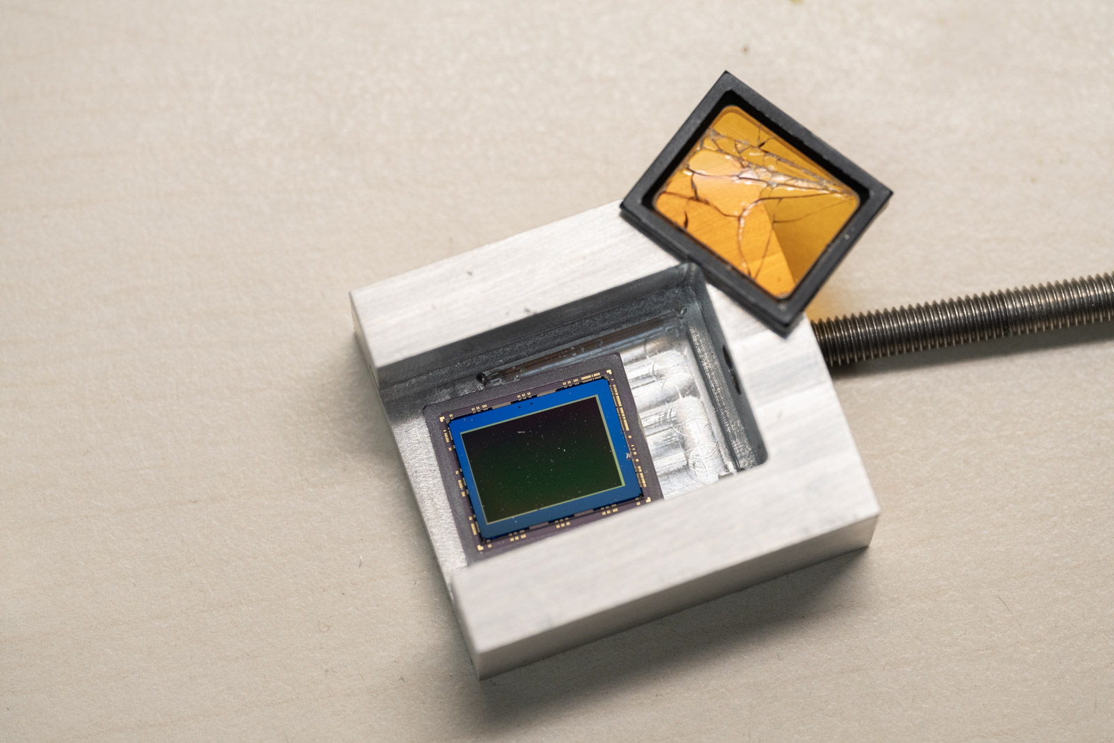
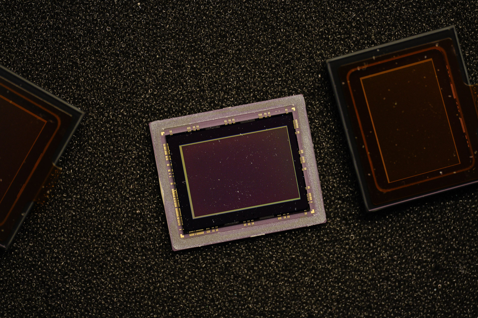
IMX283 sensor delidded vs original package:
But we finally see IMX585 monochrome version showing up, so I’ll be curious about the performance and with the ClearHDR, how much can I improve H-alpha solar full disk image capture.
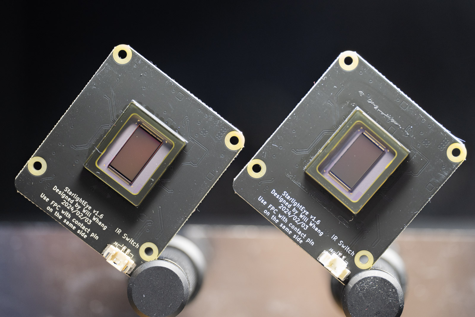
Can you really tell the difference between the two (。ŏ_ŏ)? At least I can’t, interestingly the reflection looks exactly the same. Special thanks to Soho enterprises ltd helping me getting some early samples! They have a wide range of camera modules for RPI from IMX585 to IMX662 and all the way to global shutter camera like AR0234, definitely check them out.
As for the overall telescope setup in general, while I’m content with the setup’s structure, I aim to minimize cabling and maintain a clean setup. The assembly and disassembly processes have been quite smooth so far comparing to last solar eclipse event.
Conclusion
Reflecting on the project, the timing truly couldn’t have been better. The Raspberry Pi 5 was announced just in time for me to enhance our system to record compressed RAW images that fully utilize the OneInchEye’s IMX283 sensor. This capability was something I could hardly imagine six months ago, as the CM4 was struggling just to store uncompressed RAW data. The fact that we achieved this without needing to resort to complex FPGA setups is something I’m particularly pleased with.
However, despite these advancements, there are still limitations to address. Debugging the PiSP remains a challenge, akin to navigating a black box system. Additionally, new SBCs are emerging that offer similar levels of documentation and potential improvements, which makes them worth exploring as I wait for the next solar eclipse. Where to observe it from remains an open question—Iceland or Spain, perhaps? Suggestions are welcome.
The reality I’ve come to understand is that specifications on paper do not always translate into expected real-world performance. System fabric performance continues to be a critical topic and represents a necessary trade-off to optimize costs. I hope for more comprehensive documentation on system fabric in the future to better understand and optimize it.
Over the past two years, my journey through preparing for and experiencing two solar eclipse events has been both enriching and transformative. It began with the simple goal of utilizing a 1” sensor to capture the solar eclipse, and evolved into managing multiple sensor modules and navigating significant changes in the underlying architecture between the events. This progression is truly both challenging and exciting for me.
The availability of older yet still capable sub-LVDS/MIPI-CSI image sensors, combined with the emergence of powerful single-board computers and accessible FPGA solutions, suggests that this is an excellent time for makers to explore larger format image sensors. These advancements make sophisticated astronomical imaging more accessible to a broader community, enabling enthusiasts to achieve professional-grade results without prohibitive costs.
Looking ahead, I am optimistic about the future. With new hardware continually emerging, the next two years promise even more opportunities to enhance my setup further. I anticipate not only refining the technologies I use but also expanding the scope of what can be achieved in amateur astronomy. I am eager to continue exploring these wonders with ever-improving tools at my disposal.
Footnotes for the GitHub Project Pages
For those interested in the technical details or considering building similar setups, here are the links to the GitHub repositories for the projects I’ve developed:
- OneInchEye: Explore and contribute to the OneInchEye project here.
- StarlightEye: Explore and contribute to the StarlightEye project here.
- CFE Board: Explore and contribute to the CFE Board project here.
I encourage anyone interested in these projects to build and modify the sensor boards for personal or commerical use. The primary purpose of sharing these projects is to address my specific needs while also providing a foundation for others to build upon.
If you decide to produce and sell any boards based on these designs, you are welcome to do so under the terms of the MIT license included with each project. However, I kindly request that you use a different project name for commercial products to avoid confusion and ensure that support queries are directed appropriately. This will help maintain clarity and support community engagement in a constructive and organized manner.
Leave a comment