Reading Mk4001mtd
Building a Reader for the World’s Smallest Hard Drive — MK4001MTD
Introduction
Back when flash storage was still very expensive, miniature hard drives offered a much better cost-per-gigabyte ratio. As IBM and later Hitachi produced the well-known 1-inch CompactFlash-form-factor microdrives, followed by Seagate, Western Digital, and GS Magicstor.
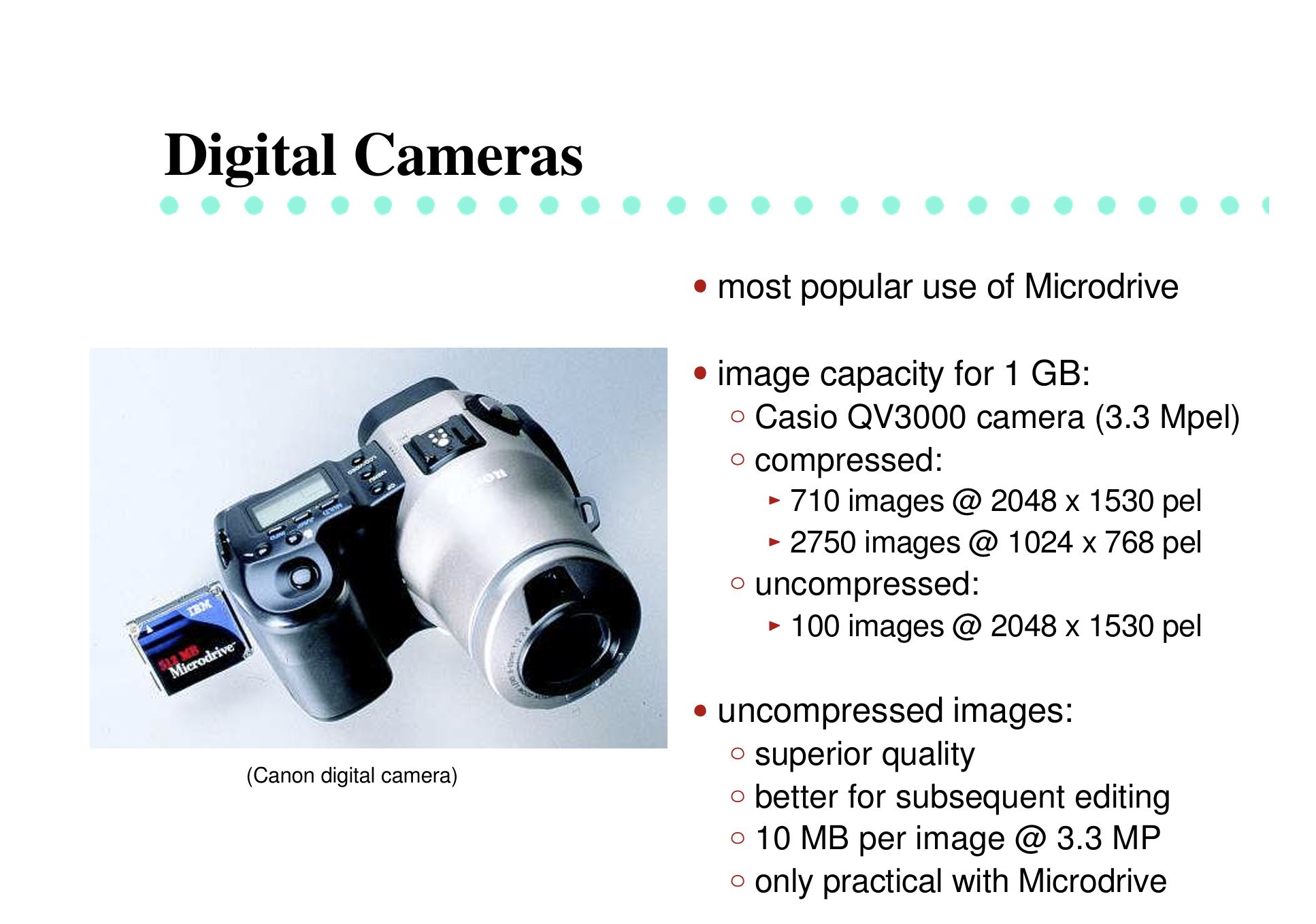
From HotChips 13 “Microdrive: High Capacity Storage for the Handheld Revolution, Thomas Albrecht (IBM)” Link:
Rather than competing directly in that same 1-inch space, Toshiba introduced something even smaller: in January 2004, it announced a 0.85-inch hard disk drive, the MK4001MTD.[1]
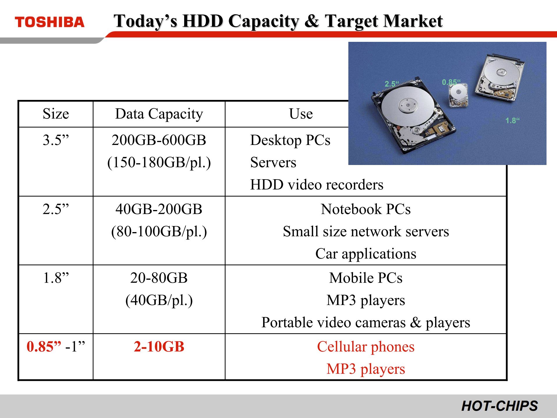
From HotChips 18 “The Ultra Small HDD for the Mobile Applications, Toshiba” Link:
This drive later appeared in products such as the Nokia N91, where it provided 4 GB of storage in a feature phone.[3] Toshiba’s 0.85-inch HDD was also recognized by Guinness World Records in 2004 as the world’s smallest hard disk drive.[2][5] Not long afterward, flash memory rapidly became cheaper, larger, and more practical, and drives like this disappeared from the market.
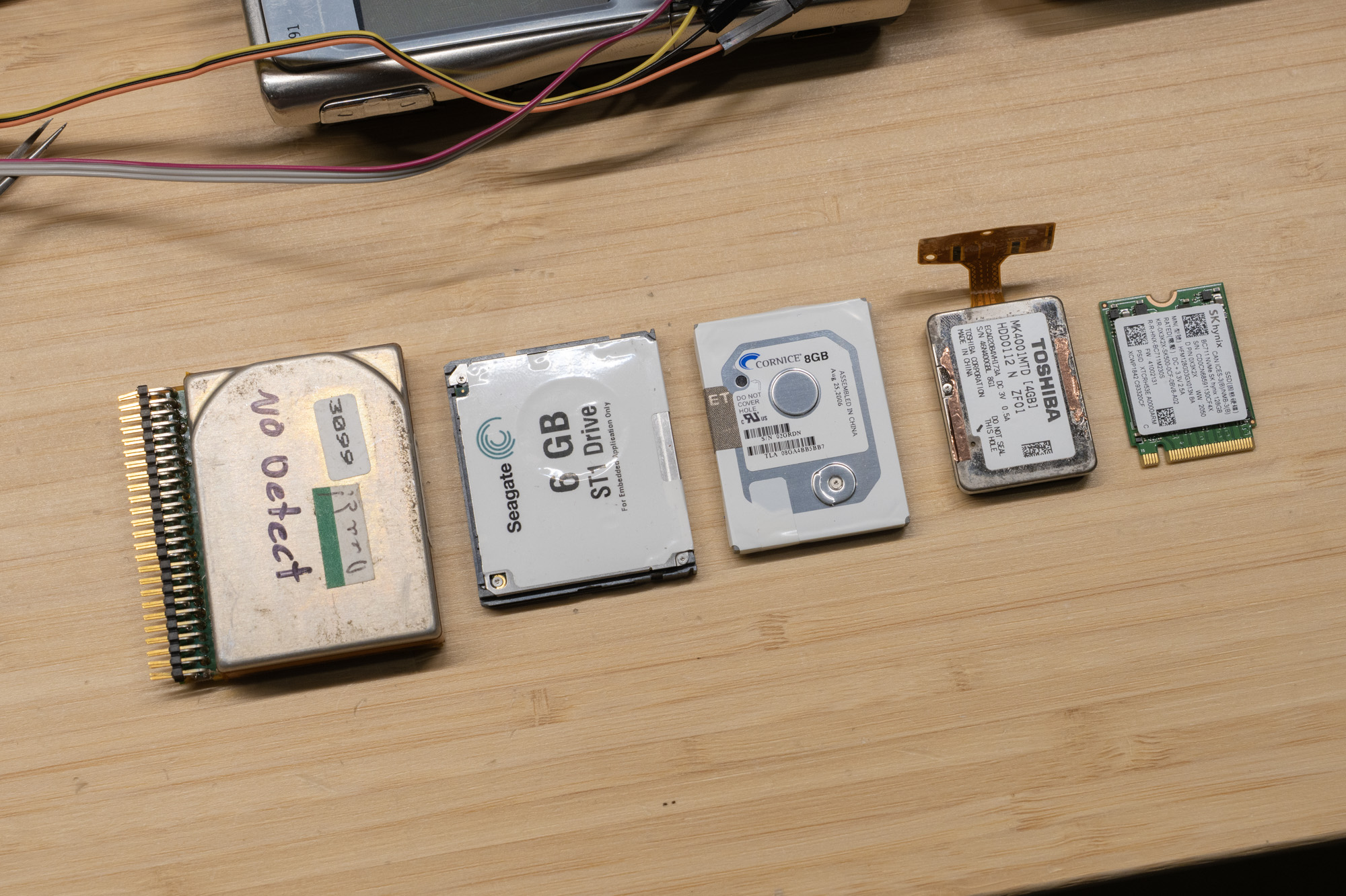 From left to right: HP Kittyhawk 1.3” (20MB), Seagate ST1 1” CF (6GB), Cornice 8GB 1” (8GB), Toshiba MK4001MTD 0.85” (4GB), and a M.2 2230 SSD (128G) as size reference
History
Over time, I collected several MK4001MTD drives whenever I came across working or even non-working units. One of my long-term goals was to figure out how to read one myself.
The first step, of course, was research. Most of what I found led back to three main sources:
- YouTube: https://www.youtube.com/watch?v=QB0KdAj54xg
- Russian forum post: https://vrtp.ru/index.php?showtopic=20791&st=0&
- EEWorld repost: https://en.eeworld.com.cn/Reference_Designs/detail/77269
Original page: https://oshwhub.com/dljy711/gl827l-card-reader
Unfortunately, none of these sources actually managed to read data from the drive successfully.
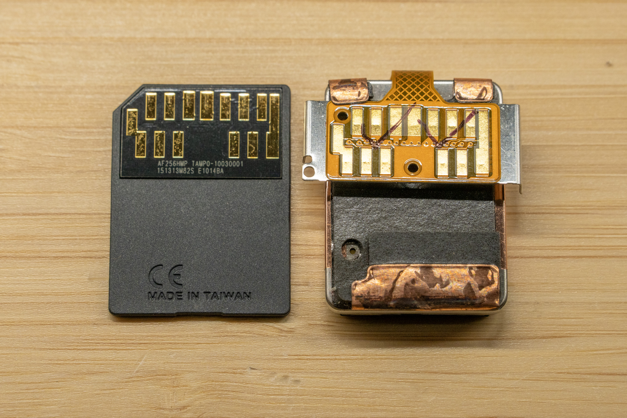
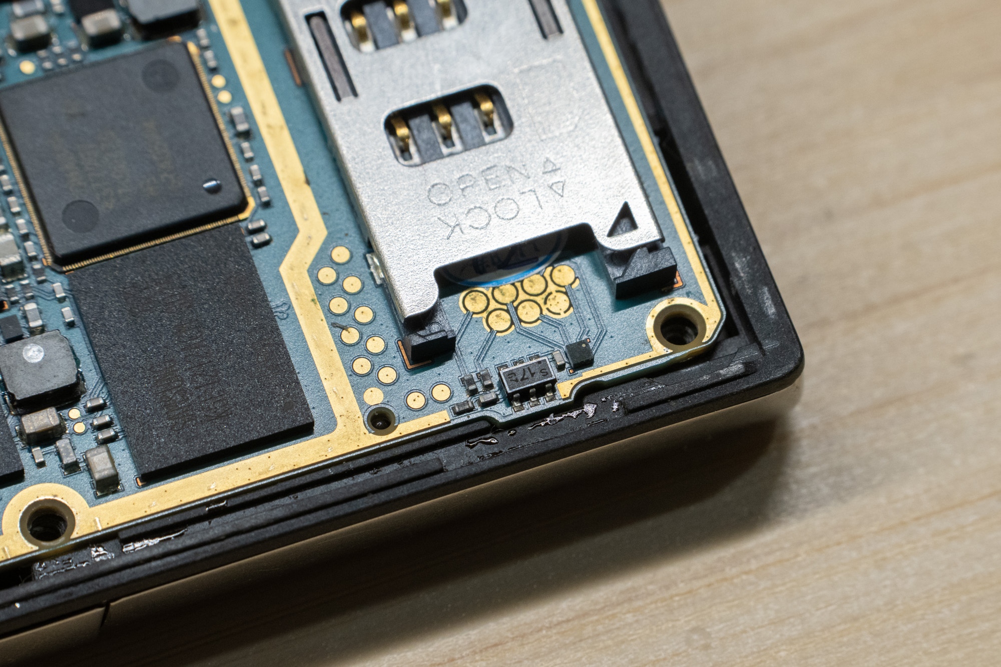
If you look at the drive itself, the pad layout looks very familiar: it resembles an MMC-style connector, but with more pads than a standard SD card. At first glance, it looks similar to MMCplus, which extended the bus width beyond the original configuration and supports an 8-bit data bus by adding four extra data lines.[4]
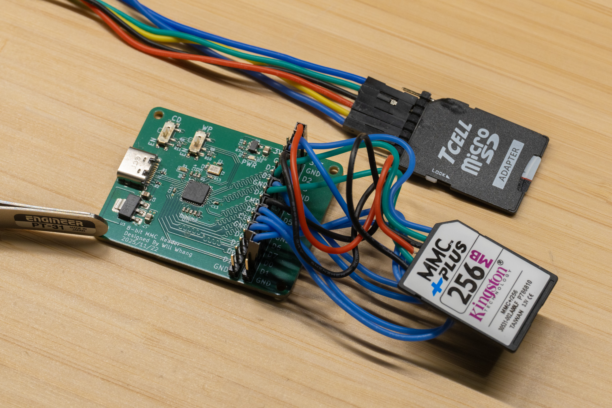
My first attempt was to connect the drive to an old microSD card reader. Like the earlier projects others has tried, it failed to read the drive. Supplying external power did not help either. Based on the comments and the connector layout, I then tried treating it like an 8-bit MMC device. Since true MMCplus readers are very rare today, and many MMCplus cards still operate in 4-bit modes, it is difficult to find hardware that genuinely supports the full 8-bit bus. Because of that, I built my own reader around the USB2240.
With real MMCPlus Card:
 With this harddrive:
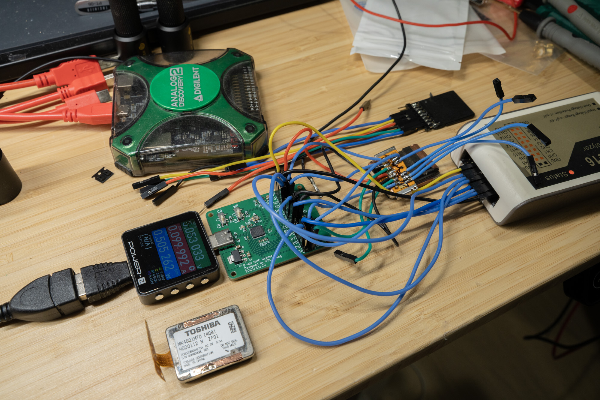
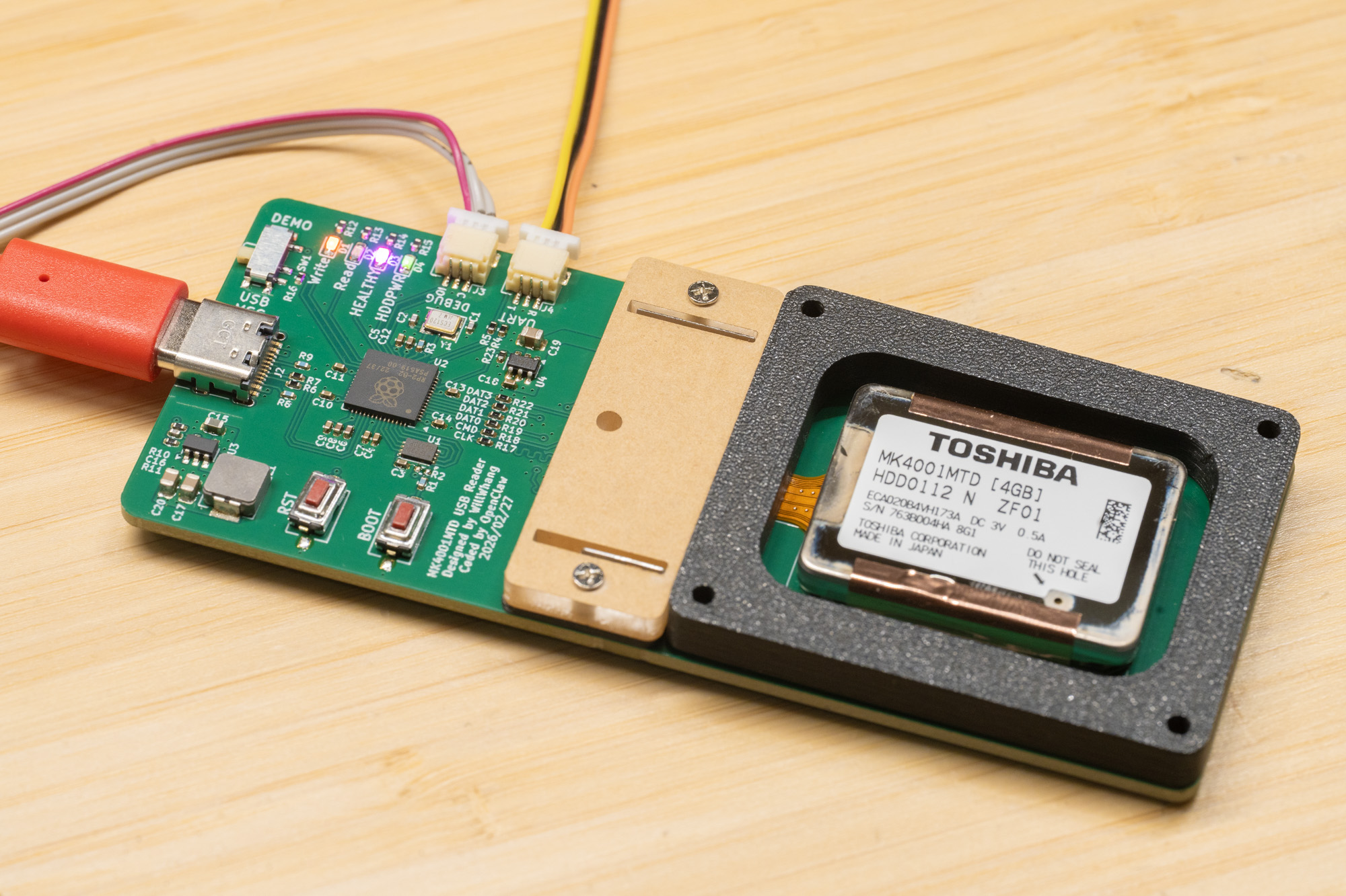
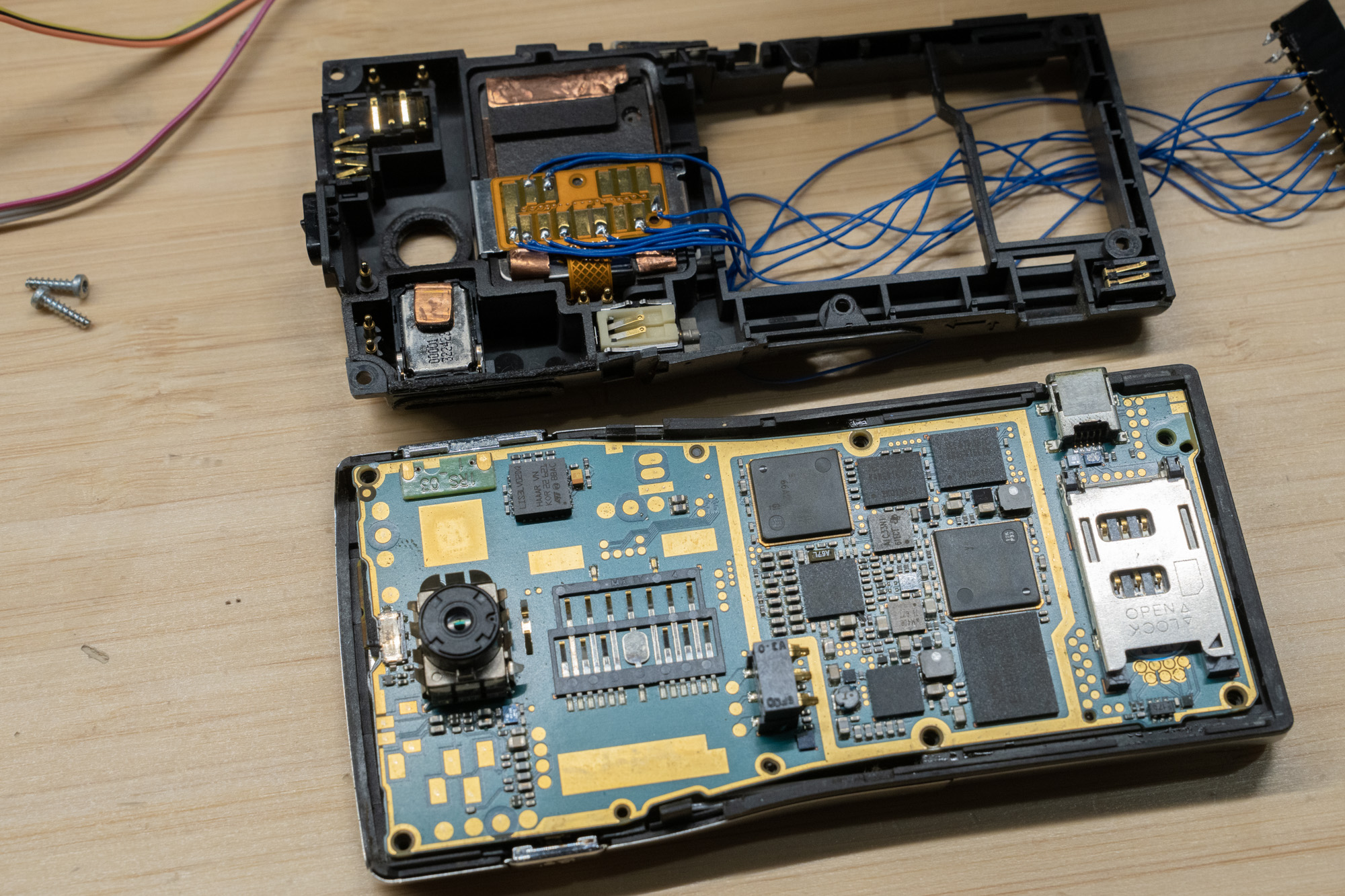
As shown above, I broke the signals out to a 0.1-inch header, with an additional row for a logic analyzer so I could see exactly what was happening and why it was failing. I even soldered an MMCplus card onto the board so I would have a known-good reference trace for comparison.
But it quickly became obvious that something strange was going on. The drive did not respond to ACMD41, CMD55, or CMD8 at all. At that point, it was clear that this was not behaving like a normal SD or MMC storage device.
Reverse Engineering
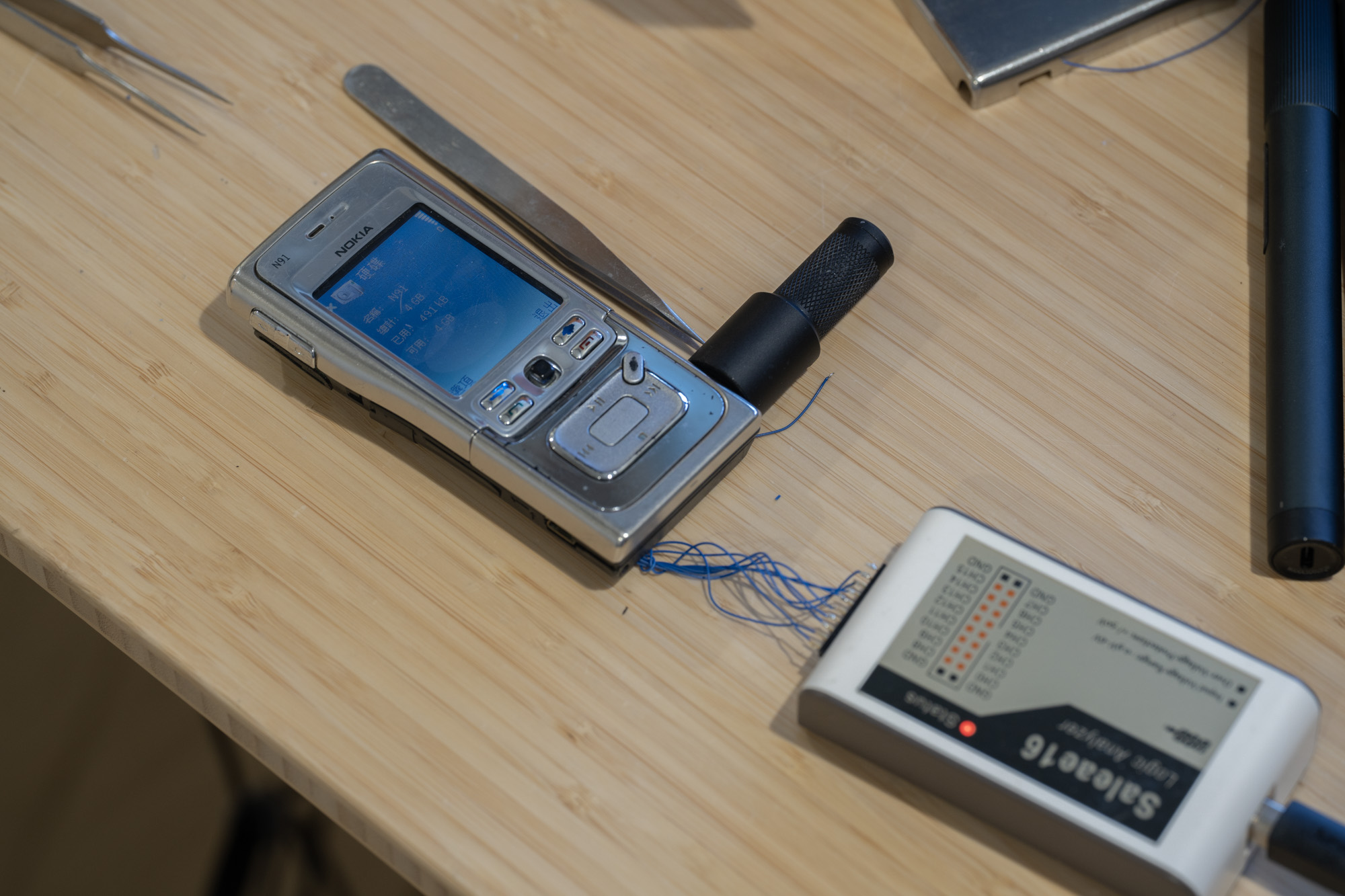
I set the project aside for a while, because what I really needed was an original host device that used the drive so I could probe the signals directly and see what the protocol actually looked like. Eventually, I came across a cheap and rather rough-looking second-hand Nokia N91 and bought it specifically for probing.
The wires were soldered slightly below the drive contacts, where the spring-contact marks were still visible, and the assembly was carefully put back together afterward.
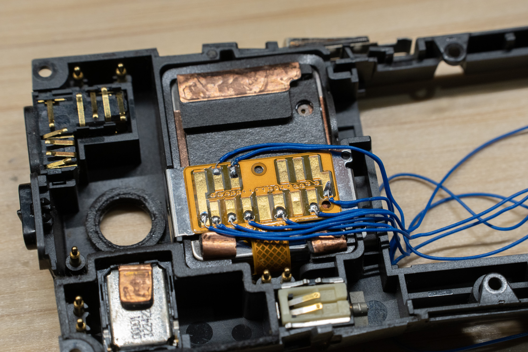
One interesting detail is that Nokia added a sensor to detect whether the back cover was attached. According to the Nokia N91 user guide, the device can stop the hard drive if the back cover is removed.[3] In practice, that meant I had to use a magnet to keep the phone happy during testing.
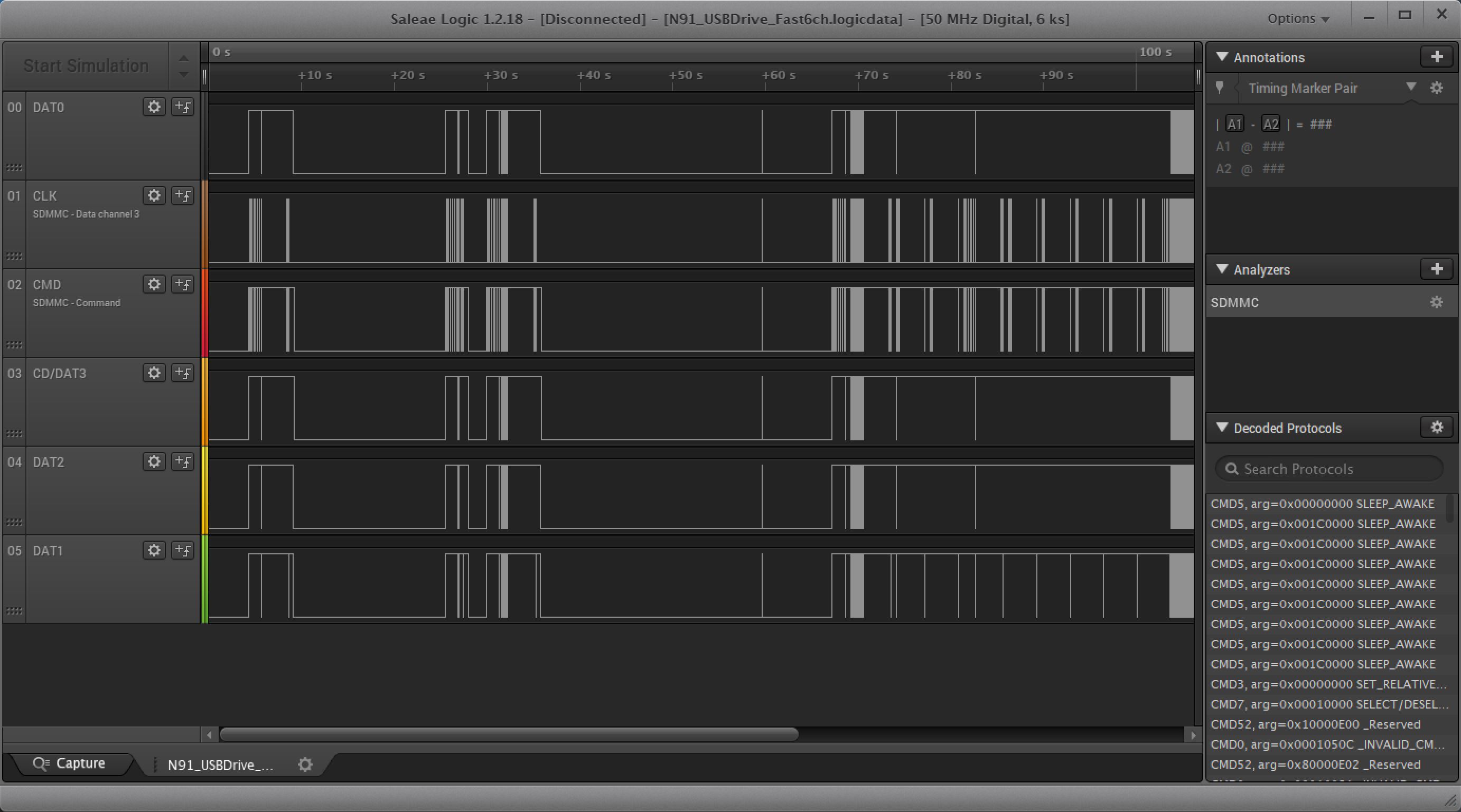
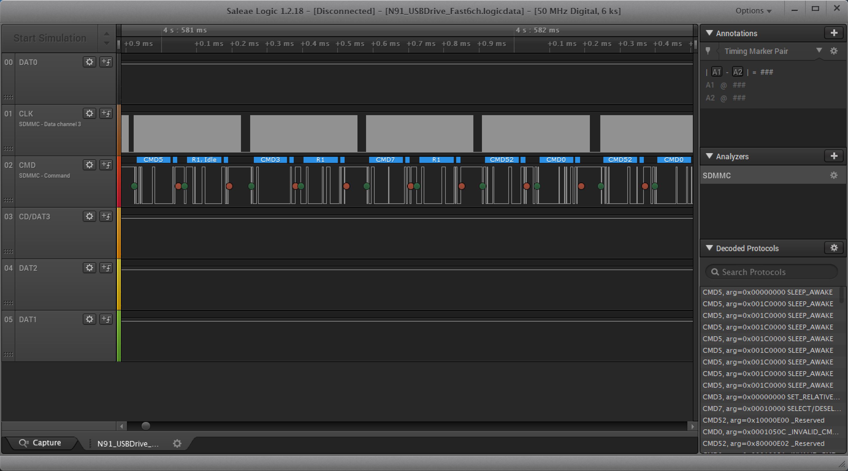
Once I got the phone to boot and captured the traces, the story finally became much clearer. The traces confirms this is a 4-bit SD/MMC interface and N91 service manual pin connection is indeed correct. The bus activity showed CMD52 traffic, which immediately pointed toward SDIO rather than a normal memory-card mode. Looking further into the command contents, it also appeared that ATA-style commands such as IDENTIFY DEVICE were being transported over that interface.
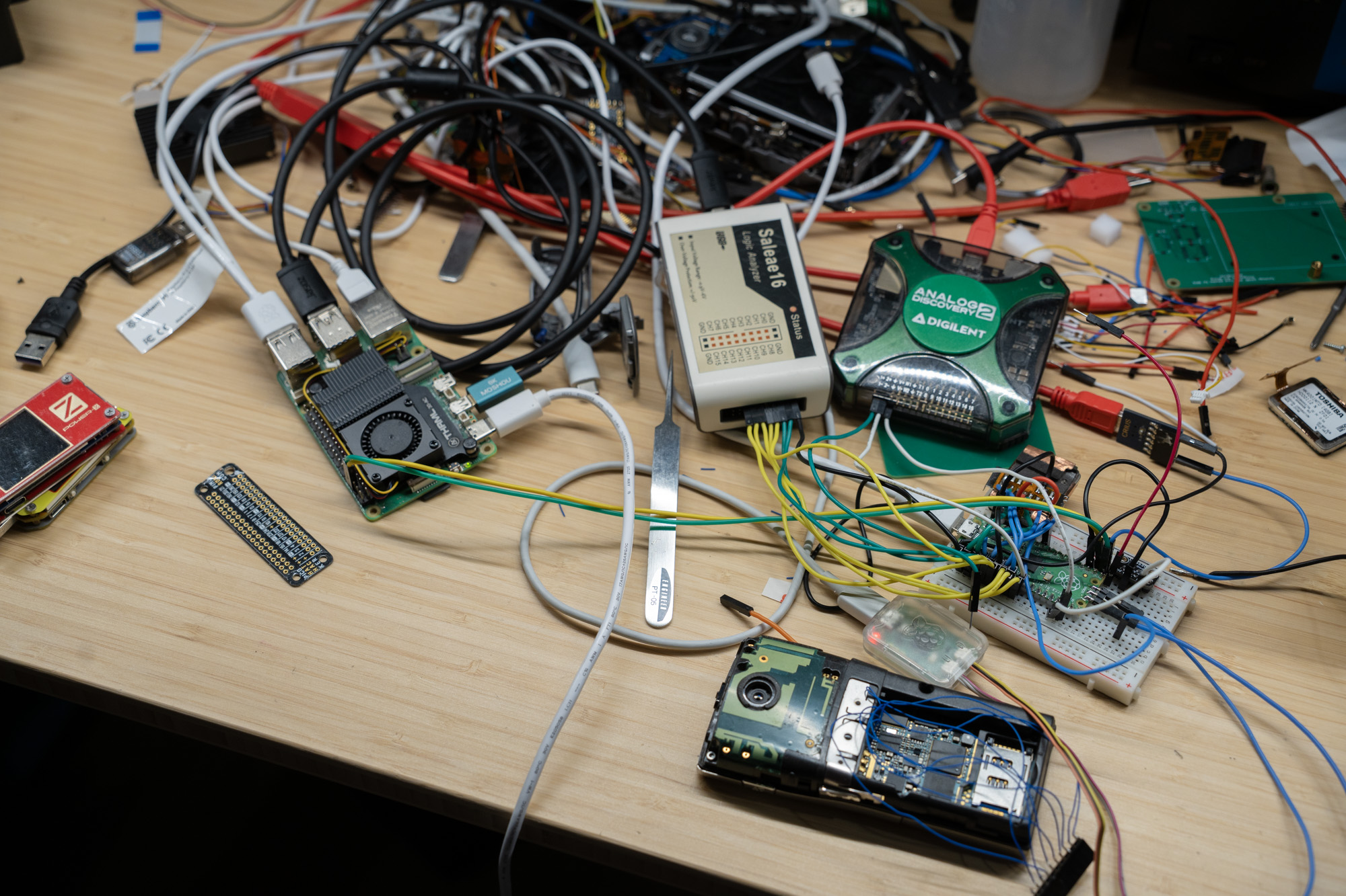
That is where OpenClaw entered the story. Once I had a rough idea of what was going on, along with several useful logic traces from the N91 during boot and USB mass-storage access, I decided to see whether OpenClaw could handle the software side and iterate on the implementation. I set up a Raspberry Pi 5 with a Pico wired to the drive, plus a Pico debugger and a logic analyzer, and gave OpenClaw the task.
And it did.
In broad terms, it successfully reverse-engineered the logic traces by building its own SDIO decoder, then wrote firmware for the Pico that exposes the drive as USB mass storage. That firmware translates USB storage requests into ATA commands and tunnels them over the SDIO interface used by the drive.
The early version used a bit-banged interface at roughly 100 kbit/s. I later asked it to move the SDIO implementation into PIO, but at that stage the model quality regressed quite a bit: it often failed to notice that the PIO code was either incorrect or too large, and even with a few reference implementations gathered from GitHub, progress was inconsistent. It did make some use of the logic analyzer, but not enough to avoid repeatedly blaming hardware problems.
Eventually, with a stronger model, it was able to sort things out. Earlier models such as GPT-5.2-Codex or Sonnet seemed to struggle with the combination of non-standard behavior, longer iteration history, and the amount of context needed to stay on track. You can actually see this in the iteration history: they would lose the train of thought and get stuck in local minima.
Yeah also it does nuke the content on the drive sometimes when doing testing.

Still, Oups 4.6 and later GPT-5.4 were able to get the project working. Once I had a functional proof of concept using a breadboarded Pico and a hand-wired drive, I decided to design a proper board specifically for the MK4001MTD.
Hardware Design
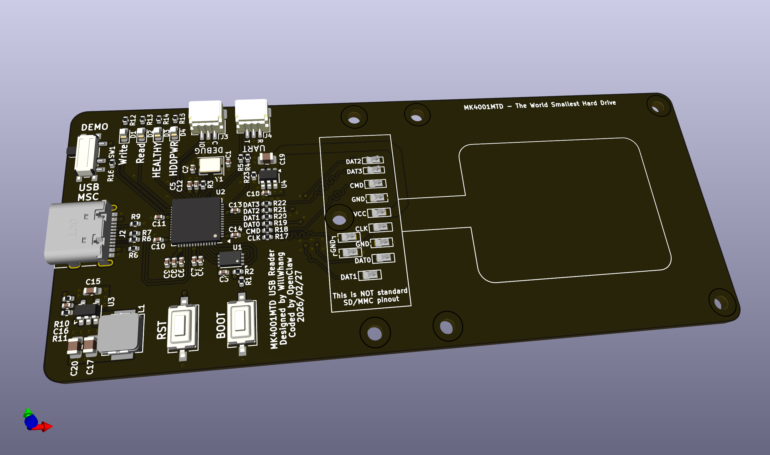
Back in KiCad, the hardware itself was fairly straightforward: an RP2040 paired with spring-loaded contacts to mate directly with the drive.
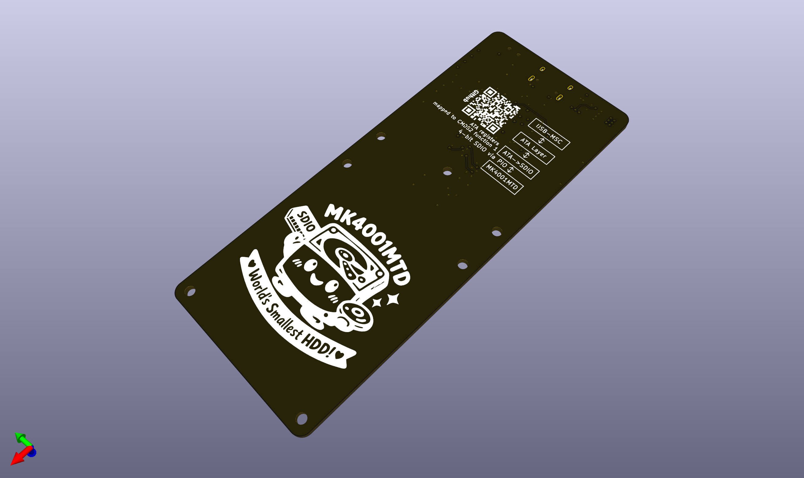
Here is the 3D model of the board:
And here the board is in pre-heating phase of soldering:
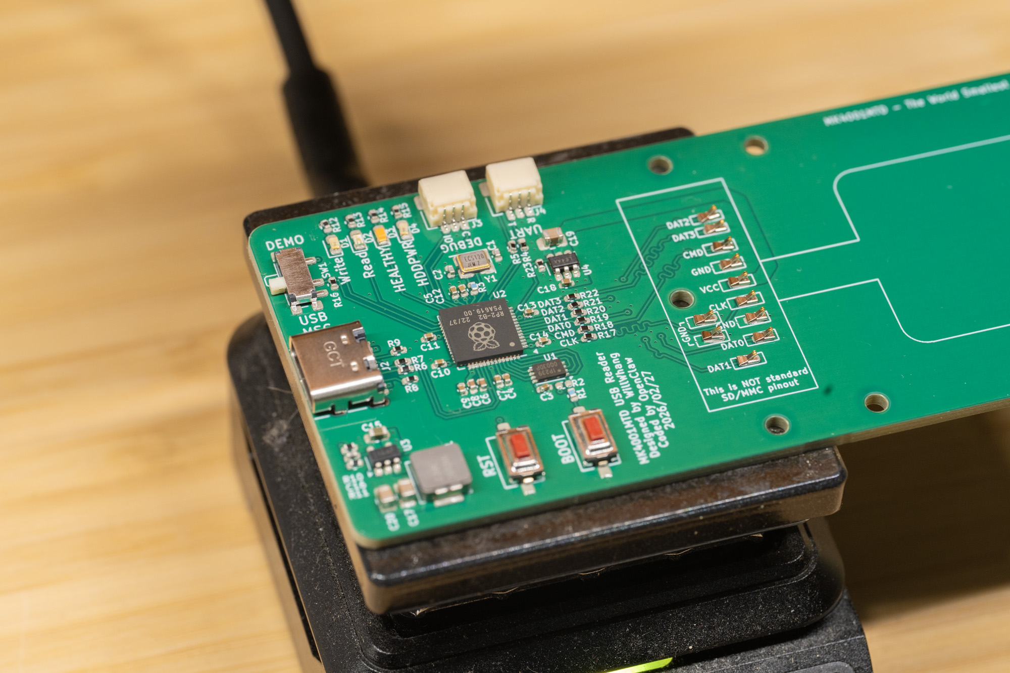
Finally we have the board done!
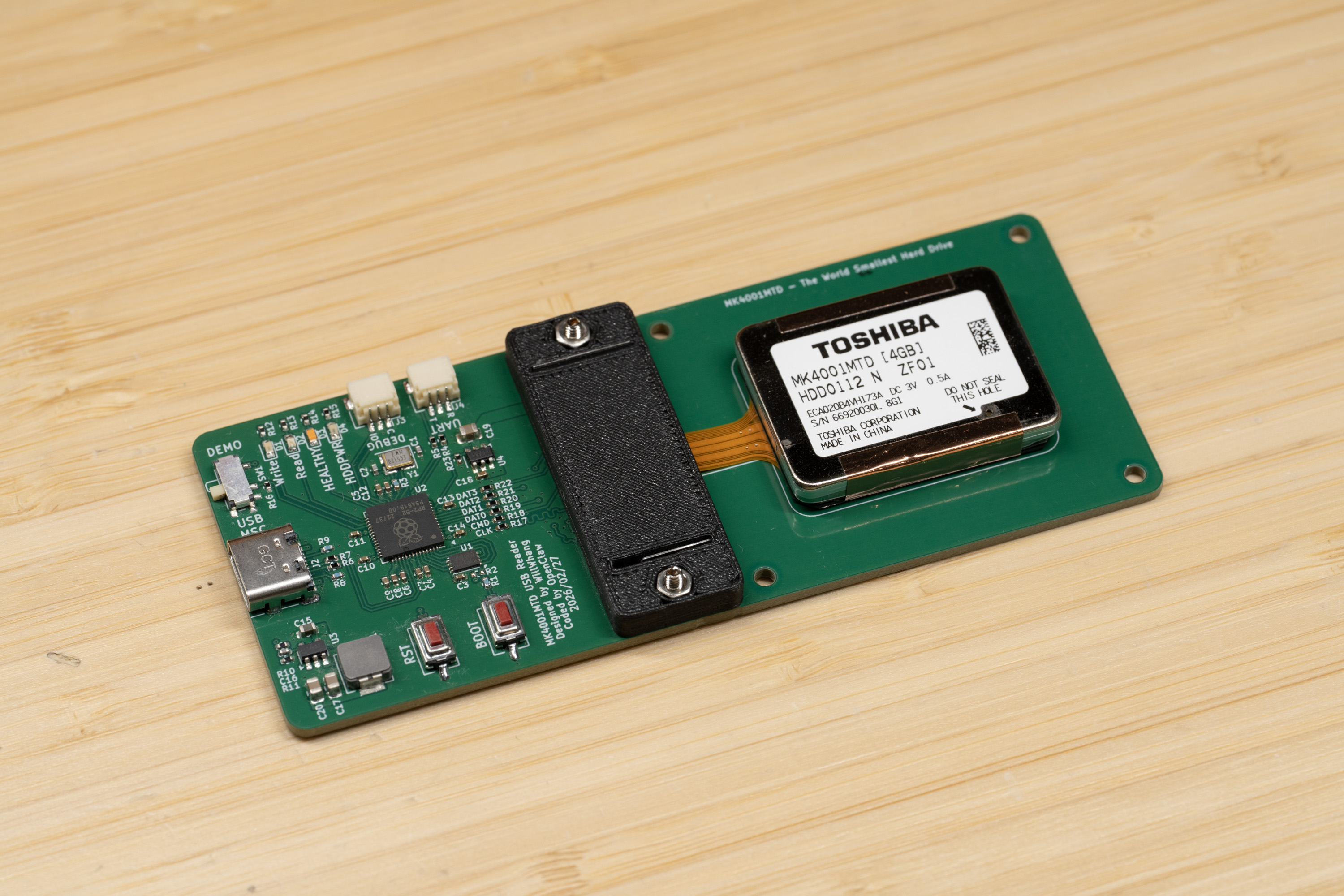
At this point you might reasonably ask: if the drive is so tiny, why is the board so large? That is a fair question. The answer is that I am trying to build something in the same spirit as my 1-inch microdrive project.
I am still waiting for the CNC-cut acrylic parts to arrive, so the final enclosure is not finished yet, and that will be updated later.
Result
I’ve set the SDIO clock to 10 MHz currently, and here is the current speed result:
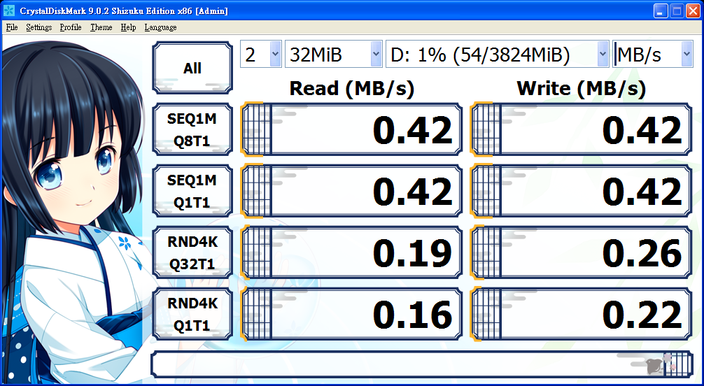
And yes, it is definitely slow by modern standards, but it is right on the edge of being somewhat usable.
Here is a quick live demonstration video:
Overall, I’m very satisfied with the result. Thankfully, Toshiba appears to have carried standard ATA commands over SDIO without adding anything too unusual. I’m also quite satisfied with how well a reasoning-focused LLM was able to handle a task like this almost independently, although it did consume quite a lot of tokens. I will definitely keep using LLMs to iterate on future projects, but it is always important to remember that they can and do break things.
Project Files
All source code, hardware design files, test scripts, and documentation for this project are available in the GitHub repository: https://github.com/will127534/MK4001MTD-USB-Bridge
The repository includes the RP2040 firmware source, KiCad schematic and PCB files, Gerbers, BOM files, mechanical models, test utilities, and supporting documentation, so the full project can be studied, rebuilt, and modified from one place.
References
[1] Toshiba, “Toshiba’s 0.85-inch HDD is set to bring multi-gigabyte capacities to small, powerful digital products,” January 8, 2004.
https://www.global.toshiba/ww/news/corporate/2004/01/pr0801.html
[2] Toshiba, “Toshiba Enters Guinness World Records Book with the World’s Smallest Hard Disk Drive,” March 16, 2004.
https://www.global.toshiba/ww/news/corporate/2004/03/pr1601.html
[3] Nokia N91 User Guide, section “Hard drive.”
https://fcc.report/FCC-ID/QEYRM-43/610530.pdf
[4] MultiMediaCard Association, MMCplus application note, April 12, 2005.
https://www.mikrocontroller.net/attachment/101561/AN_MMCA050419.pdf
[5] Guinness World Records, “Smallest hard drive.”
https://www.guinnessworldrecords.com/world-records/79075-smallest-hard-drive
Leave a comment